
Building Information Modeling (BIM)
Interoperability Issues
in Light of Interdisciplinary Collaboration
Voytek Pniewski MSc AIA
London, United Kingdom
Building Information Modeling (BIM)
Interoperability Issues in Light of Interdisciplinary Collaboration
by Voytek Pniewski, MSc AIA
with contributions from Phil Molyneux, Faculty of Business and Law, Kingston University London UK
Published by
Collaborative Modeling Ltd.
www.collaborativemodeling.com
Third Edition, 2011
Copyright © 2010-2015 by Collaborative Modeling Ltd.
The AEC (Architecture, Engineering, Construction) industry and the related processes employed during planning, designing, building, manufacturing, occupying, maintenance, as well as the demolition of facilities all involve data and information that is used for a wide variety of purposes during the project lifecycle. With the complex nature of AEC projects today, these processes engage multiple organisations, numerous stakeholders, such as interdisciplinary professionals, often spread around the world, utilising specialist and diversified computer applications and systems. In order to effectively support the use of information, organisations need to be able to represent their project data in a common interpretable form, which provides a facility of an accurate exchange of data among different computer systems and platforms. This study has investigated current state of interoperability between software applications used in BIM (Building Information Modeling) in conjunction with collaborative delivery of projects by interdisciplinary teams within the AEC industry. Key attention was paid to the de facto format for BIM models, IFC (Industry Foundation Classes). It has been recognised that methods and tools for representation of project data need to take into account modern concepts of project delivery, like concurrent engineering, collaborative product development, or IPD (Integrated Project Delivery). The methodology to investigate the research problem in this Research Report involved digital model prototyping and testing in a given workflow to examine model integrity. It has utilised fifteen different software applications, ranging from the popular and free-of-charge Google SketchUp to the state-of-the-art CATIA V5 solution by Gehry Technologies: Digital Project. Over fifty digital models have been produced and incorporated in the work, and approximately one hundred and fifty pieces of literature have been examined to assure the accuracy of the information provided. The work has adopted a problem-solving approach by analysing the implications for standards in the AEC area, identified specific interoperability issues, and returned a set of recommendations and practical solutions leading to the improvement of interdisciplinary collaboration in BIM.
Voytek Pniewski is a hybrid professional with a solid architectural, engineering and construction foundation, blended with Business Information Technology formal education and experience. He is a Registered Architect, professionally affiliated with the American Institute of Architects. He is a leader and a promoter of Architecture Engineering, Construction (AEC) technology, including Internet based collaboration tools, BIM (Building Information Modeling), interoperability among AEC software applications, and IPD (Integrated Project Delivery) approach.
Voytek Pniewski has over 30 years of experience in construction industry working with owners, land developers, design consultants and principal contractors on a wide variety of international projects of various value, including in excess of $1 billion in a single undertaking. During this time he has gained vast range of knowledge in management, design, construction, and the delivery process techniques in projects in the USA, the Virgin Islands, Poland and the UK. He has worked with varying contractual arrangements in commercial, retail, residential, educational, leisure, hospitality, and industrial sectors. He has been involved in all stages of projects, from early stage development / pre-construction to the full completion and facility management. Through travel and projects located in different countries and continents he has gained knowledge of international standards and developed excellent communication skills with people of many nationalities and various ethnic backgrounds.
Contents
Chapter 2: Review of Previous Work
Chapter 3: Aims and Research Questions
Chapter 4: Methods of Investigation
4.1 Introduction / General Approach
Chapter 5: Testing, Discussion, and Findings
5.1 Introduction: Unfolding Interoperability Issues
5.2 Setting Criteria and Commencing Tests
5.3 Assembling and Testing Interdisciplinary Model
5.4 Other Interoperability Issues
Appendix 1 - Supporting Documents
Main Text
Figure 1: Factors influencing the use of BIM (Young et al., 2007)
Figure 2: IFC Object Model Architecture Diagram (buildingSMART, 2009a)
Figure 3: Generation of XML file from CAD or IFC file (Qizhen et al., 2001)
Figure 4: Start-Up Model (native ArchiCAD 3D model plan view opened in ArchiCAD) with 2D overlay
Figure 5: Start-Up Model of an apartment - native ArchiCAD file opened ArchiCAD
Figure 7: Sample model server - Secom IFC Model Server architecture (Adachi, 2010)
Figure 9: Interdisciplinary collaboration workflow process map (Weise et al., no year)
Figure 10: Start-Up Model IFC file opened with IFC File Analyzer (partial)
Figure 11: IFC Start-Up Model opened in Solibri Model Viewer
Figure 12: IFC Start-Up Model opened in DDS-CAD Viewer
Figure 13: IFC Start-Up Model opened in Nemetschek IFC Viewer
Figure 14: IFC Start-Up Model opened in IFC Engine Viewer
Figure 15: IFC Start-Up Model opened in ArchiCAD
Figure 16: IFC Start-Up Model opened in Digital Project
Figure 17: IFC Start-Up Model opened in Vectorworks
Figure 18: IFC Start-Up Model opened in MicroStation
Figure 19: IFC Start-Up Model opened in Revit
Figure 20: IFC Start-Up Model opened in Constructor
Figure 21: IFC Start-Up Model opened in SketchUp
Figure 22: Architects-Detail Design model, Design Development, Digital Project - CATProduct file
Figure 23: Architects-Detail Design model, Design Development, Digital Project - IFC file
Figure 25: Envelope Designers model, Envelope Design, Vectorworks - IFC file
Figure 26: Civil and Structural Engineers model, Structural Engineering, MicroStation - IFC file
Figure 27: Building Services Engineers model, Mechanical & Plumbing, Revit - IFC file
Figure 28: Specialist IFC models from interdisciplinary team before the assembly
Figure 29: Fully assembled interdisciplinary IFC 3D model
Figure 30: ifcXML file generated from 3D model with data direct extraction approach
Figure 31: Saving ArchiCAD file in IFC2x3
Figure 32: ArchiCAD IFC2x Units settings
Figure 33: ArchiCAD IFC2x 'Export' settings with '2D Elements' option selected
Figure 34: ArchCAD IFC2x 'Export' settings with '2D Elements' option unselected
Figure 35: ArchiCAD IFC2x Custom Pset settings
Figure 36: ArchiCAD IFC2x Exterior settings
Figure 37: ArchiCAD IFC2x Person and Organization settings
Figure 38: ArchiCAD IFC2x Miscellaneous settings
Figure 39: Native ArchiCAD model, 2D view opened in ArchiCAD
Figure 40: IFC file errors (with '2D Elements' option selected) in DDS-CAD Viewer
Figure 45: Start-Up Model - IFC file (with 2D Elements option selected) 2D view opened in ArchiCAD
Figure 49: Autodesk Revit MEP error and warnings message
Figure 50: Warnings posted prior to opening the model in Autodesk Revit MEP
Figure 56: IFC File Analyzer, Start-Up Model - Summary sheet
Figure 57: IFC File Analyzer, Start-Up Model - Header sheet
Figure 58: IFC File Analyzer, Start-Up Model - IfcColumn sheet
Figure 59: IFC File Analyzer, Start-Up Model - IfcSlab sheet
Figure 60: File Analyzer, Start-Up Model - IfcWall sheet (part 1 of 4)
Figure 61: File Analyzer, Start-Up Model - IfcWall sheet (part 2 of 4)
Figure 62: File Analyzer, Start-Up Model - IfcWall sheet (part 3 of 4)
Figure 63: File Analyzer, Start-Up Model - IfcWall sheet (part 4 of 4)
Figure 64: File Analyzer, Start-Up Model - IfcWallType sheet
Figure 65: ArchiCAD IFC2x Export settings with Extended Properties selected
Figure 68: Start-Up IFC model opened in Constructor
Figure 69: Start-Up IFC model opened in Constructor - details
Figure 72: Start-up IFC model opened in SketchUp with IFC2SKP plug-in
Figure 73: IFC File Analyzer: Generating spreadsheet from Start-Up Model IFC file
Figure 74: IFC File Analyzer: Excel spreadsheet generated from Start-Up Model IFC file
Figure 75: File Analyzer: Excel spreadsheet listing objects with a non-standard IfcPropertySet
Figure 76: SketchUp IFC Psets of Start-Up Model
Figure 79: SketchUp IFC Pset of Start-Up Model revised
Table 2: Software utilised in the research
Table 3: Start-Up Model - Solibri Model Viewer examination
Table 4: Start-Up Model - DDS-CAD Viewer examination
Table 5: Start-Up Model - Nemetschek IFC Viewer examination
Table 6: Start-Up Model - IFC Engine Viewer examination
Table 7: Start-Up Model - ArchiCAD examination
Table 8: Start-Up Model - Digital Project
Table 9: Start-Up Model - Vectorworks
Table 10: Start-Up Model - MicroStation
Table 11: Start-Up Model - Revit
Table 12: Start-Up Model - Constructor
Table 13: Start-Up Model - SketchUp
Table 14: Architects (AR_DD) model - Digital Project (revised Table 8)
Table 15: Examination results - summary
1.1 Introduction
This study has investigated current state of interoperability among software applications used in BIM in conjunction with collaborative delivery of projects by interdisciplinary teams within the AEC industry. The work also has analysed implications for standards in this area, identified specific interoperability issues, and made recommendations leading to improvement of interdisciplinary collaboration in BIM.
The choice of the subject was driven by Authors observations of the AEC industry while being involved in real estate development, design and construction management projects. These observations have resulted with the view that the AEC industry greatly lacks efficiency and it is in a desperate need of improvement. This is in light of the current economical climate, attention to sustainability, zero-tolerance to project related injuries and incidents that are linked to design and construction methodologies, and the patterns indicating a trend of deepening single-persons professional responsibility.
Reaching back to the history, teams in past would produce their information using pencil or ink and exchange sheets of paper capturing their designs. Together with the agreed set of standard drawing conversions and person-to-person office or site communication this formed very interoperable system. With the widespread adoption of digital technology this interoperable system was exchanged for a system incorporating new methods and tools that substituted the proven ways of working. This new system however, requires redefinition of the business processes, articulation of peoples communication, its tools, to make sure that pieces of technology utilised in projects not only talk to each other but seamlessly converse with people. Undergoing technological and methodological changes became very visible in the AEC industry during the last decade. The drive for adoption of new technologies is explained by companies desire - and pressure - to become more productive, cost effective, quality conscious, creative, and innovative in designing, building, and operating facilities.
Interoperability issues in BIM in light of interdisciplinary collaboration may be seen as a modern story of the Tower of Babel. For centuries people have been involved in designing and building facilities. It was found however, that the processes utilised, the time and cost involved, the quality obtained, and the financial returns no longer meet requirements. By utilising technology, people now would like to address these new demands and build a city or a structure with its top in the heavens (Encyclopaedia Britannica eb.com, 2010, p.1). As an analogy, based on the description found in Encyclopaedia Britannica eb.com (2010), the teams however, have been disrupted by confusing languages of the projects stakeholders, until they no longer could understand one another. Although the story of the Tower of Babel ends on leaving the project unfinished, this Research Report explores the ways allowing the team members to successfully complete the work they started, still utilising the different languages employed.
AEC projects today are complex and involve a wide range of specialism areas, which lay beyond traditional architectural, structural, and mechanical & electrical disciplines. These professional areas could be identified as masterplanning, infrastructure, geotechnical, facades, access & maintenance, wind, fire, traffic, acoustics, lighting, accessibility, renewable energy, environmental, sustainability, IT & communications, standard detailing, landscape, health & safety, security & risk, facility management (FM), to name a few. In addition, projects demand expertise in modern planning/scheduling, cost, and quality assurance. All of this requires strong interdisciplinary teams with stakeholders willing to collaborate, including clients and their representatives, designers, contractors, and the range of specialist consultants with their deep domain knowledge and experience.
Professionals, even equipped with highest expertise, would not succeed in modern projects without sophisticated methods and tools. Management techniques today recognise the necessity of collaboration and there are many proved approaches in place today to satisfy the demands. These techniques are almost in every case associated with information technology tools - software solutions in particular. BIM and its increased visibility since the beginning of the last decade captures the technology and the advances of the AEC processes. With the vast amount of specialised software applications on the market, the build teams are striving to extend the new technologies and processes into their collaborative projects. As people are subject to dialog and to understanding of each other - the software applications need to do the same. Most of the software programs however, were originally developed to work as standalone applications and are not typically designed to share data with other programs (Young et al., 2007). Different tools would normally have their proprietary data structures and often do not provide means of linking their database through a standard, which creates the biggest challenge to interoperability (Douglas, 2010).
Such a lack of interoperability or perhaps interoperability illusion, greatly contributes to deficiencies and errors in the AEC industry. A 2004 cost analysis prepared by RTI International (Health, Social, and Economic Research) and the Logistic Management Institute for NIST (The National Institute of Standards and Technology)[1] estimates the cost of inadequate interoperability in the U.S. government facilities industry being in the reign of $15.8 billion per year, representing between one and two percent of the industry revenue.
The chapters of the Research Report are structured to effectively take the reader through the journey of the research, from the research background to the discussion and the conclusions. The chapters may be reviewed independently, as each one generally contains introduction, the main body and the conclusions. Appendices contain mostly auxiliary information and additional detail intended for the most dedicated enthusiasts of the subject (Mador, 2008).
Chapter 1 identifies the focus of the research. It provides introduction to the research problem and the background, plus develops reasons for the research aim and the research questions. It further enables the reader to understand the background to the findings.
Chapter 2, through literature review, informs the reader what is already known about the research problem. It provides background to the findings and justifies the research questions and methods. It leads the reader, step-by-step, to the research questions.
Chapter 3 expends on the aims of the research and details the research questions. A total of ten questions, or rather groupings of questions, have been identified, and these are based upon the aims of the research. The research has anticipated generating the answers or recommendations to the questions listed. The chapter concludes with the research limitations and hypotheses.
Chapter 4 provides detailed description of investigation methods and illustrates how the data was collected. It graphically introduces model prototyping and testing methodologies.
Chapter 5 comprehensively addresses the testing and findings. It commences with unfolding interoperability issues and transits into rich illustration of interoperability testing through evaluation of models in the AEC industry, utilising several BIM computer applications with numerous screenshots and tables to document the process. The findings are comprised of the answers to the research questions.
Chapter 6 has provides conclusions to the accomplished work. It outlines the anticipated future of interoperability in BIM applications.
This work is not without limitations. Vast amount of software and management approaches in existence today has allowed only a handful of scenarios to be evaluated. As there is no agreed one set of methods in place to test interoperability, the work has been settled on the best-to-the-knowledge prototyping and model integrity checks. Many areas of interoperability are just emerging, which in some cases limits access to the research materials. Not all the standards listed in Section 2.2 Literature Review were evaluated in testing, with the reasons summarized in sub-section Data Models / Specifications / Standards. Finally, the time frame allowed for the Research Report and the volume limitation of the paper has permitted for investigation of selected areas only.
1.2 Research Context
The focus of the research is interoperability among software applications used in BIM in conjunction with collaborative delivery of the AEC projects by interdisciplinary teams. With its own data structures for representing models, their elements, attributes and properties, the software programs utilised in BIM - even equipped with good translators - may not necessary meet expectations in terms of exchange project data that is useful or necessary. There are known issues with interoperability, most of them generalised in technical literature. What it is not quite certain, is what specifically these issues are, their impact, and how to effectively address them.
This Research Report makes a distinction between the research-related areas that have been already investigated by others with the answers available through technical literature reviews, and the contrasting areas without easily available or convincing answers in place, requiring other methods of investigation. Hence, the literature review in this Research Report comprises of general the knowledge about BIM, the AEC industry, team structures, collaboration, management approaches, AEC software applications, data models, and the related standards. The items that require alternative methods of investigation, like testing or sampling, are represented in the Research Report by a set of research questions related to (1) interoperability specific issues and methods of disclosing them, (2) compliance criteria intended for model integrity checks, (3) software vs. interoperability standards, (4) interoperability vs. efficiency and accuracy of information retrieval, (5) value of interoperability and its quantification, (6) definitions of a good standard, (7) maturity of interoperability standards, (8) reliability of standards, (9) areas of interoperability improvement, and (10) interoperability obstacles.
The research identifies specific interoperability issues, gains understanding of such issues, and adopts a way forward for reliable BIM systems we can utilise with trust. The research further recognises imperfections in the interoperability solutions that are in place today, and takes the issues forward by primarily concentrating on the advancements and the benefits they bring, rather than deficiencies.
In summary, the subject research has been a journey from much generalised interpretations of interoperability issues in BIMs interdisciplinary collaboration, involving literature review, detailed digital model prototyping and testing, and arriving with clear understanding of the specific issues and the resolving them in practice.
This chapter informs the reader what is already known about the research problem by answering initial set of questions, not specifically listed within this document, which may be raised regarding the subjects background and its general areas. These areas are BIM and its software applications, interoperability, standards, interdisciplinary collaboration, workflows, project stakeholders, to name a few. The chapter employs comprehensive literature review and provides background to the findings and justifies the research questions and methods. It further leads the reader, step-by-step, to the research questions.
2.1 Theoretical Background
Prior to the commencement of the research, a number of prospective areas were considered for investigation. This was in preparation for an accurate definition of the research problem and justification of the research questions and methods. The review has allowed for confirming and documenting what was already known about the research problem pot forward for discussion in Section 2.2 Literature Review. The issues that needed further investigation through alternative approaches were therefore separated and included in Chapter 3 under Section 3.3 Research Questions, becoming the subject of the testing and findings as illustrated in Chapter 5.
2.2 Literature Review
The knowledge gained through the literature review is communicated in the areas listed in this section. This knowledge directly pertains to the research problem and it is a prerequisite to the majority of the research material presented in this Research Report. Large volume of technical material was reviewed for the purpose of the research and the close attention was paid to fully cite the reference sources, as seen in the text and in the main body of the Research Report under References section. Apart from the above mentioned specific reading material, a vast amount of supplementary literature has been also reviewed to gain general knowledge, and these resources are listed in Appendix 2 - Bibliography section. Bibliography includes all the references combined with the general reading material, and such the listing is intended to direct the reader towards the additional reading to gain further knowledge about the subject.
Building Information Modeling (BIM)
According to the BuildingSMART Alliance (2010, p.1) the National Building Information Model Standard defines BIM as follows; Building Information Modeling (BIM) is a digital representation of physical and functional characteristics of a facility. A BIM is a shared knowledge resource for information about a facility forming a reliable basis for decisions during its lifecycle; defined as existing from earliest conception to demolition. BIM is not strictly limited to its model geometry but it is about the complete information pertaining to a facility, normally included in project design drawings, specifications, product data sheets, calculations, programmes/schedules, cost analyses, sustainability guidance, health & safety directives, fabrication drawings, as-built drawings, operation & maintenance manuals, etc. BuildingSMART Alliance (2010, p.1) further describes BIM as A basic premise of BIM is collaboration by different stakeholders at different phases of the lifecycle of a facility to insert, extract, update or modify information in the BIM to support and reflect the roles of that stakeholder. BIM, including its interchanges, is based on shared digital representation and interoperability principals allowing computer-to-computer exchanges with use of open standards. BIM represents various meaning depending on its use, i.e. (1) when applied to a project, BIM constitutes information management, (2) when utilised by the design team, BIM represents integrated design, and (3) when used by project stakeholders in general, BIM constitutes an interoperable process for project delivery (buildingSMART Alliance, 2010). The overall goal of BIM is to create a dynamic model of a facility that can be used by the stakeholder teams throughout the buildings lifestyle (Young et al., 2007).
BIM is specifically intended for the AEC industry to provide benefits to the all parties involved in planning, design, construction, facility management, and demolition of facilities. Such parties normally include architects, engineers, contractors, fabricators, facility operators, as well as owners (Eastman, 2009).
BIM represents 2D design information and most importantly 3D objects that carry their geometry, relations and attributes. When put together, these objects form a building model, a sub-product of BIM. BIM design tools allow for extracting a range of views from the building model for design, reference, checking, and other purposes. These views are automatically consistent since each object instance is defined only once, i.e. a building elevation and a plan of an external wall constitute the same object, or are composed from the same objects, but only presented in alternative views. BIM design tools define objects parametrically, meaning that the objects are defined as parameters and relations to other objects. Any change to an object causes automatic change to the corresponding one. Parametric objects re-build themselves - automatically - in accordance with the rules embedded in them (Eastman, 2009). Example would be a change in the size of a window with the automatic adjustment of the corresponding wall opening to accommodate new window geometry. This functionality and parametric modeling in general is illustrated while building and testing prototypes in Chapter 5: Testing, Discussion, and Findings and Appendix 1 - Supporting Documents.
Apart from 2D and 3D, BIM is capable of carrying other multi-dimensional models, such as 4D and 5D. 4D model incorporates the dimension of time used to visualise and manage construction programmes/schedules. 5D BIM model employs cost data, automates quantity takeoffs for cost estimating, and if coupled with 4D could be used for cash flow analyses (The American Institute of Architects, 2007a). No firm agreements are yet in place to the additional dimensions in BIM, such as 6D, 7D, etc. Authors view is that additional dimensions could be incorporated in the model to add other areas of the AEC, such as health & safety or sustainability to begin with.
BIM gains continuous popularity. Is adoption headed towards a tipping point in 2008, attracting more participants, and the range of factors influencing the use of this technology is shown in Figure 1 (Young et al., 2007).
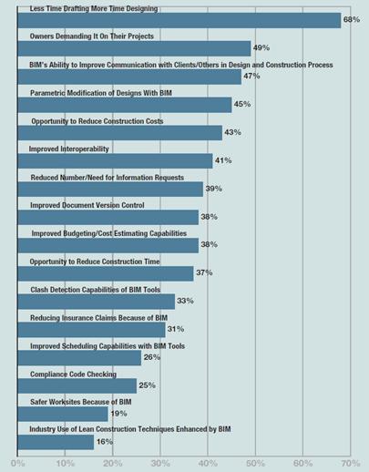
Figure 1: Factors influencing the use of BIM (Young et al., 2007)
Project Stakeholders and the Project Approach
Based on the research study of the construction market in the North America, architects are the leading champions of BIM and the heaviest users of this technology among the team members surveyed in the report by Young et al. (2007). The report further shows that engineers follow in the footsteps of architects with their increased use of BIM; nearly half of them use it for structural analyses. Only 13% of contractors count BIM among their frequently used applications, which constitutes half of the architects and one-third of engineers. Close to half of owners have never used BIM - the opportunity which has not been fully realised yet.
With the current use of BIM, there is no published evidence of companies fully and successfully utilising it by adopting such a variety of software solutions in a single project as the prototyping and testing steps undertaken in this Research Report. With companies increasingly understanding BIMs potential and its importance, there is a desire to exchange more diversified specialism data, and therefore the need to understand the necessity of employing a wider range of software solutions, the corresponding interoperability tools, and the processes.
The interdisciplinary team established for the purpose of the prototyping and testing in this Research Report is comprised of a number of stakeholder groups, and these are listed in Table 1.
Table 1: Project stakeholders
|
NAME |
ABBREVIATION |
RESEARCH SPECIFIC INVOLVEMENT |
|
Employer |
EM |
Client, client representative, project management |
|
Architects-Concept Design |
AR_CD |
Architectural design - Start-Up Model |
|
Architects-Detail Design |
AR_DD |
Architectural design - development of model[2] |
|
Civil & Structural Engineers |
ST |
Structural design |
|
Building Services Engineers |
BS |
Sanitary and ventilation design |
|
Envelope Designers |
ED |
Facade and balcony design |
|
Contractors |
CM |
Constructors |
|
Others |
OS |
Other consultancy, manufacturing, FM services |
In contrast to individual effort in completing the design tasks, as seen in traditional manual process of project delivery, the stakeholders in this research have adopted the approach to deliver their interdisciplinary design in a collaborative fashion requiring continues exchange of information during various stages of the project. This approach could be compared to a process of concurrent engineering adopted by many non-AEC industries, characterised by overlapped interactions between functional areas during all phases of system development (Nicholas, 2008). Such process has been found very successful, has penetrated the AEC industry, to be finally transformed into the approach known as IPD (Integrated Project Delivery), which continuously gains its popularity in the AEC industry. As defined by the American Institute of Architects (2007b, p.1) IPD is a project delivery approach that integrates people, systems, business structures and practices into a process that collaboratively harnesses the talents and insights of all participants to reduce waste and optimize efficiency through all phases of design, fabrication and construction. The IPD team usually includes members extending well beyond traditional owner, designer and contractor roles, that penetrates into all project phases not strictly limited to design and construction.
Interdisciplinary teams which are put into tasks of collaborative project delivery utilising BIM, together with its range of specialist, very often highly technical software solutions, are going through the challenge of adjusting from traditional highly linear and manual process of project delivery they are familiar with. As noted by Khemlani (2007), in the integrated and collaborative scenario, multiple stakeholders need to adjust their mind-sets of individual project delivery and develop self-interest to channel their decisions to the cause of the larger, common good. Technology challenges are also the issue for the teams, as many of them are accustomed to traditional project delivery using pencil, paper and verbal communication, having difficulty in comfortable adoption of information technology solutions. Such challenges, despite the technology being more accessible, easier to use, often intuitive, and affordable, could be only overcame by continuous education, self-desire, and interest to be part to this, sometimes radically new, way of working. This leads to Research Question 9 further discussed in chapters to come and pertaining to interoperability in BIM, how BIM is affected by the various approaches of interdisciplinary design delivery, and what are the recommendations on how to improve interdisciplinary collaboration in general.
Software Applications Utilised in the Research
There have been a number of criteria used to select the software applications utilised in this research. The key criterion has been the popularity of the software packages among the varying professionals involved in the AEC industry. The choice was based on Authors experience and knowledge gained through his involvement in architecture, engineering and construction. The consultants and the software applications they utilised have been chosen for illustrative purposes only. The consultants may vary from project to project and the software usage may go beyond of what has been shown in this research. The software applications utilised in the research are summarised in Table 2 and can be divided into two groups: (1) production tools for the project stakeholders, i.e. applications that are used for production of design information, and (2) viewers, i.e. IFC viewers, normally free-of-charge solutions used for visual examination of the files and checking integrity of the translators.
Table 2: Software utilised in the research
|
USER |
SOFTWARE |
WEBSITE |
DESCRIPTION |
|
All |
Solibri Model Viewer Build Number: 6.0.0.565 Java Version: 1.6.0_21 Supported OpenGL Version: 2.1.2 Free download
|
http://www.solibri.com/ |
Free of charge software build for viewing and examination of IFC files. |
|
All |
DDS-CAD Viewer Version 6.5 Release build 29/6-2009 Free download
|
http://www.dds-cad.net/132x2x0.xhtml |
Same as above |
|
USER |
SOFTWARE |
WEBSITE |
DESCRIPTION |
|
All |
Nemetschek IFC Viewer Version V3.2.0 Professional XXL Free download
|
http://www.nemetschek.co.uk/ ifc |
Same as above |
|
All |
IFC Engine Viewer Version 1.11 beta Free download
|
http://www.ifcbrowser.com/ ifcengineviewer.html |
Same as above |
|
All |
Solibri IFC Optimizer Version number: not available Free download
|
http://www.solibri.com/solibri-ifc-optimizer.html |
Free of charge software used to optimise IFC files by removing redundancies and updating the references (Solibri Inc., 2010).
|
|
All |
IFC File Analyzer: Version 1.33 Updated on: 8 July 2010 Free download
|
http://ciks.cbt.nist.gov/cgi-bin/ctv/ifa_request.cgi |
Free of charge software used to generate Excel spreadsheets from IFC files. The spreadsheets list each type of entity with its attributes. Multiple files can be analysed at once and their entity usage compared (Lipman, 2009).
|
|
All |
SketchUp (Google SketchUp 7): Version 7.1.6860 IFC2SKP plug-in (Secom Co. Ltd., 2010) Version 0.8.5 Free download
|
http://sketchup.google.com/ |
Popular free of charge design and presentation software. |
|
All |
IFC2SKP Plug-in (Secom IFC2SKP Plug-in): Version 0.85 Beta Free download
|
http://www.ohyeahcad.com/ ifc2skp/index.php |
Free of charge plug-in allowing import of IFC files into Google Sketchup 6 and 7. |
|
EM |
Solibri Model Checker: Workstation License Version 6.0 Build Number: 6.0.0.640 Evaluation license
|
http://www.solibri.com/ |
Software specifically intended for IFC files, checks integrity of model, with functionality like quantity take-offs and clash detection. |
|
AR_CD |
ArchiCAD (Graphisoft ArchiCAD 13): Version 13.0.0 Windows 32-bit Build Number 3600 Library Build Number 3479.147 IFC 2x3 Add-On Commercial version
|
http://www.graphisoft.com/ |
Leading software intended specifically for architects with add-ons available for building services, sustainability, and facility management. Purchased by Nemetschek (Vectorworks vendor) in January 2007. |
|
AR_DD |
Digital Project (Gehry Technologies Digital Project): Version 1 Release 4 Service Pack 7 Build Number 19 CATIA Version 5.19 Student version
|
http://www.gehrytechnologies.com/ |
Powerful multidisciplinary modeling software using Dassault Systemes CATIA as a core engine. Intended for AEC and manufacturing industry. |
|
ED |
Vectorworks (Nemetschek Vectorworks): Version 2010 Service Pack 4 Build 126481 Licensed Products: Designer and Renderworks Student version
|
http://www.nemetschek.net/ |
Leading software intended specifically for architects. One of the advantages over other popular software applications is it affordability. |
|
ST |
MicroStation (Bentley MicroStation V8i): SELECT series 1 Version 08.11.07.171 Academic version
|
http://www.bentley.com/en-US/Products/MicroStation/ |
Leading multidisciplinary software for the AEC industry. |
|
BS |
Revit (Autodesk Revit MEP): Version 2010 Student Version
|
http://usa.autodesk.com/adsk/ servlet/pc/index?siteID= 123112&id=6861034 |
Leading mechanical, electrical and plumbing software and the well known Autodesk brand. |
|
CM |
Constructor (Vico Office Suite): Version 2008 SP2 INT - Version EDU, dedicated
|
http://www.vicosoftware.com/ products/Vico-Office/tabid/ 85286/Default.aspx |
Purpose-built software for construction. |
As the key factor in selecting the software applications for the purpose of this research has been their wide adoption, the view was taken to utilise Windows-based platform only, instead of Mac. The majority of AEC applications are Windows-only and according to Khemlani (2010), Mac versions are not yet available for some of the packages utilised in this research, like Bentley MicroStation, Revit, and NavisWorks.
The literature review has provided sufficient answers to a range of interoperability issues. Some of the issues required additional investigation and generated queries. One of the unanswered questions pertained to the extent the software applications contribute to interoperability issues, and whether these are caused by the standards. This topic is raised in Research Question 3, along with other unanswered software-related items, such as issues pertaining to comparison of interoperable files generated by different software applications, and software vendors racing towards adaptability of solutions offered by standards bodies.
Interoperability
Individual software applications store information in their native formats, imposing challenge in the AEC industry. In order to make the information available to project stakeholders, the software applications utilised need to have a facility of accurate data exchange. There are different methodologies, software systems, and information and communication technologies to address effective exchange of data between software applications. They range from middleware software, exchange file formats developed by individual proprietary software vendors such as DXF (Data eXchange Format), standards and open-specification data models like XML (eXtensible Markup Language), IFC (Industry Foundation Classes), Web Services, deployed for distributed databases ICT (Information and Communication Technology), project model servers, and semantic Web applications (Yang and Zhang, 2006).
According to Gallaher et al (2004, p.ES-1) interoperability is defined as the ability to manage and communicate electronic product and project data between collaborating firms, and within individual companies, design, construction, maintenance, and business process systems. This definition, originated from the NIST, makes a reference to managing and communicating the information, but without providing details to any specific workflow or whether the information is simply passed to others, put in a central depository, or exchanged. This point is evaluated further in conjunction with tools, processes, standards, and specifications intended for resolving interoperability issues, as illustrated in sub-section Data Models/ Specifications/ Standards below.
Interoperability issues in the AEC industry cannot be easily resolved without a set of rules and principles for classification of information requirements into data exchange specifications. The issues are being deepened by the complexity of the building information models, wide range of specialisms and vocabularies in the AEC industry, the increasing amount of computer software applications, and the management practices employed (The National Institute of Standards and Technology, 2010a). Interoperability issues could not be addressed without a careful identification of investigative methods. These methods and the interoperability issues subject to investigation are captured in Research Question 1.
The initiative towards resolving interoperability issues comes in a great measure from proprietary software vendors. It is to their interest to advance the software programs and address the customer needs directed towards interoperability. According to Young et al. (2007) the promise of improved interoperability ranks among the factors that have the greatest influence on the decision to get involved in BIM (refer to Figure 1 for details). Over sixty percent of the AEC industry lists software incompatibility as the primary factor impacting team members ability to share information electronically. Software vendors are well aware of the statistics, and will respond to the market to win the customers. The value of interoperability is further addressed by Research Question 5, which brings the issue of its importance, its affect on interdisciplinary collaboration in BIM, and provides quantification of interoperability issues.
There needs to be a level of reliance, trust and control of models integrity by the team stakeholders and the teams need to be assured that the building information model is compliant with the set of users requirements. This issue has been captured in Research Question 8. Any references made within the text to compliant model, refer to the models integrity when compared with the one generated using the original model authoring application. Further on, compliant model does not constitute a compliant design. Model integrity on the other side, characterises a model converted to one of the standard interoperable extensions like IFC or ifcXML, with no meaningful deviations from its source model created with the original model authoring application.
There is a wide range of factors contributing to lack of interoperability. Research Question 10 raises this issue and looks into the answers by identifying specifics to the obstacles and the resolution of interoperability issues.
Standards / Data Models / Specifications
Standards ensure desired characteristics of products and services, such as quality, reliability, efficiency, and interchangeability within an expected cost parameters. Lack of standards is noticeable in products that are unreliable, of poor quality, and made of components that do not fit or are incompatible with other components expected to work together. When products, systems or devices work well it is most likely because they meet certain set of standards (International Organization for Standardization, 2010b). This applies to architecture, engineering and construction as well, where continuous efforts are being made to standarise data exchanged in workflows in this industry. These standardisation initiatives are led in Europe by IDM (Information Delivery Manual) and in the USA by NIBS (The National Institute of Building Sciences through NBIMS Project (The National BIM Standard Project) (National Institute of Building Sciences, 2010).
With the popularity and success of WWW (World Wide Web) it would be inappropriate not to examine the approach of the international community W3C (The World Wide Web Consortium) in light of development of standards used in WWW. These standards are developed under the authority of W3C called specifications or recommendations, and it is up to the users to follow them or not (Hunter et al., 2007). W3C is a group of organisations, the public, and the full time staff, lead by individuals like the inventor of the Web Tim Berners-Lee, working in unity on developing Web standards (W3C, 2009a). W3C have recognised that to assure long-term growth of the Web it is important to develop a set of protocols and guidelines which would follow a certain set of principles. These principles guide the W3C work and are about Web for all, Web on everything, vision, Web on rich interaction, Web of data and services, and Web of trust. These areas capture W3C primary goals of human communication, commerce, participation, knowledge sharing, and building trust, also availability to all people, despite what hardware, software and network infrastructure they use, and with no barriers to the language they speak, their culture, geographic location, and their abilities (W3C, 2009b). The best known contribution to the Web by W3C is the HTML 3.2 04 4.01 Recommendations, the XML 1.0, the XSLT and XPath Recommendations. The wide implementation of recommendations is reasoned by the adopted process of creating standards by open invitation to any company or individual through the W3C membership. XML is the base recommendation upon which the whole XML family of standards is built on (Hunter et al., 2007). The relevant standards have been summarised in the sub-sections below.
ISO (International Organization for Standardization)
As described by International Organization for Standardization (2010a) ISO is a non-governmental organisation comprised of national standards institutes, being the worlds largest developer and publisher of international standards. Since founding it in 1947, ISO members from 163 countries had developed over 18,000 international standards. ISO objective is to make products and services, particularly their development, manufacturing and supply, more efficient, safer and cleaner. ISO standards also promote innovation, share technology and practices, provide safeguard to consumers, facilitate trade between countries, and provide governments with a basis for legislations. ISO standards are voluntary but often they may become a market requirement.
STEP (Standard for the Exchange of Product)
STEP, also known as ISO 10303, it is an international standard capable of describing product data independently from any particular system and throughout the lifecycle of a product, from design to manufacturing, using it, and the disposal. STEP contributes to a neutral file exchange used as a base for storing and sharing product database. STEP has led to improvements in CAD (Computer Aided Design) and its model development practices and overall product data quality. It has been also instrumental in fostering collaboration and communication within supply chain teams. Since its beginnings in 1984, STEP is being continuously developed, used in various industries including AEC, aerospace, automotive, and shipbuilding (International Organization for Standardization, 2010c).
CIS/2 (CIMSteel Integration Standards)
According to the National Institute of Standards and Technology (2010b) CIMSteel Integration Standards (CIS/2) is the product model and electronic data exchange format specifically intended for structural steel information. CIMSteel stands for the Computer Integrated Manufacturing of Constructional Steelwork, which integration standard covers the complete flow of information from design, through manufacturing, to site erection. CIS/2 is a truly international effort, endorsed by the American Institute of Steel Construction in 1998 after it was developed by the Steel Construction Institute in the UK, and further developed by Georgia Institute of Technology in the US as a format for data exchange between software applications used for steel design, analyses, engineering, fabrication, and construction. CIS/2 is not an executable software application but a format of files that are imported or exported in a steel-related CAD or BIM software.
(IFD) International Framework for Dictionaries
IFD is the mechanism or standard developed by ISO (ISO 12006-3:2007), allowing for creation of multilingual dictionaries or anthologies (buildingSMART, 2010e). It provides flexibility by allowing for the link between the model and the various databases used within the project (IFDWeb, 2010).
IDM (Information Delivery Manual)
IDM is another recent development that captures and integrates BIM business procesess and provides for the business process detailed specifications (buildingSMART, 2010d). It describes the process undertaken within design and construction and provides information required for execution of such process. The IDM overall intent is to provide a basis for reliable information exchange among the project stakeholders (buildingSMART, 2009d).
XML (Extensible Markup Language)
As described in (Evjen et al., 2007), XML is a standard for data representation which was created 1998 with the W3C initiative to form a markup language representing data for use and consumption regardless of the platform. The idea of XML is to mark up a document such a way that it could be understood across all working boundaries. This is instrumented by adding descriptive text to the items contained in the document so another application can make a meaning of it. The means of creating and presenting markup in XML are relatively easy, which contributes to gaining its popularity.
Leading to IFC and ifcXML
The standards discussed above have influenced, or were influenced by, IFC and ifcXML, the solutions specifically intended for the AEC industry. As the subject of this Research Report is concerned with interoperability in BIM, IFC followed by ifcXML needed to find sufficient coverage in this paper and is discussed in the separate section 2.3 IFC and Link to XML.
2.3 IFC and Link to XML
Interoperability related work in the Research Report concentrates on AEC-wide standard specification: Industry Foundation Classes. IFC-based interoperability relates to sharing data throughout the project lifecycle, globally, across disciplines and across technical applications" (buildingSMART, 2009b, p.18).
The initial IFC[3] specification was created in 1995 and is written using the EXPRESS data definition language, which is identical to the one used in STEP and CIS/2 (buildingSMART, 2009c). IFC was developed by buildingSMART[4] and is a common data schema intended for holding interdisciplinary information for building lifecycle in a building information model, and exchanging it among software applications used in AEC (buildingSMART, 2010f). A schema, often called Product (Data) Model, is captured in IFC specification, and composed of (1) entities or classes, (2) attributes, and (3) relationships between entities. Schema defines the way by which the population of these entities and relationships needs to be represented. Building information model may be also called populated data model or project data model, and constitutes a population of a schema. The model follows the patters, templates and any constraints defined by the schema and contains the actual instances of the entities (buildingSMART, 2009b).
The architecture diagram of the IFC model shown in Figure 2 illustrates its four distinct conceptual layers, as per International Alliance for Interoperability (1999): (1) Resource Layer that forms the lowest layer in IFC model architecture. Resources are characterised as objects which do not rely on any other classes in the model. It provides Resources classes used by classes in the remaining layers, and expresses the basic attributes and properties such as geometry, quantities, measurements, material type, construction durations, costs, etc.; (2) Core Layer constitutes Core project model and provides the Kernel[5] and a number of Core Extensions, and contains entities for products, relationships, processes, etc., (3) Interoperability Level provides a set of modules or entity categories defining objects that are common across AEC interdisciplinary applications, and finally (4) Domain/Application Layer, the highest layer of the IFC Object Model providing a set of specific modules intended to use in specific AEC applications linked to the individual specialisms.
|
|
_______________________
(4) Domain / Application Models Layer
_______________________
(3) Interoperability Layer
_______________________
(2) Core Layer
_______________________
(1) Resource Layer
_______________________
|
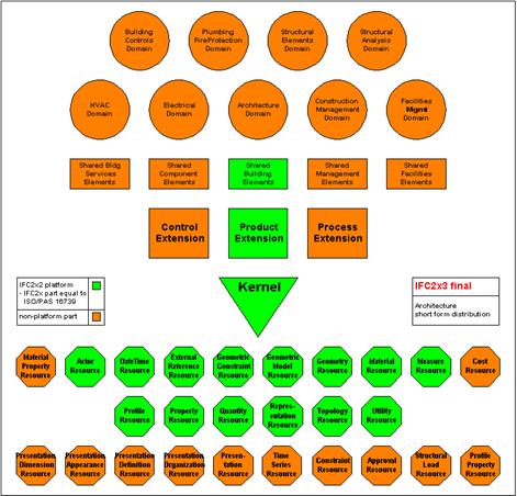
Figure 2: IFC Object Model Architecture Diagram (buildingSMART, 2009a)
IFC offers a facility to enhance flexibility and extensibility of its model. This is instrumented with the use of (1) Property Sets known as Psets, and (2) Proxies (Khemlani, 2004). Psets belong to entities that have been defined in the IFC model and are comprised of properties, such a U-value[6] of a facade, fire rating of a wall, cost of flooring material, etc. Proxies are newly formed entities that have not been defined with the given IFC model, and constitute of the geometry and Psets, similarly to regular pre-existing entities.
The IFC Object Model involves a large set of object definitions, but the individual speciality end-user applications implement only parts of it. To effectively support data exchange such applications need to be equipped with identical or overlapping parts or subsets of the IFC Product Data Model. Such subsets are called IFC Views, or Data Exchange Use Cases, and comprise of individual IFC objects, IFC Psets, and any other defined specific object definitions (Gökce et al., 2007). The IFC view is a subset of the IFC schema, containing data specification for a particular model exchange scenario (buildingSMART, 2009b).
In addition to the Object Model being the foundation of IFC, the previously discussed under sub-section Standards/ Data Models/ Specifications IFD and IDM play significant role in interoperability. IFD constitutes important mechanism for creation of dictionaries, and IDM provides for BIM business process detailed specifications. Both standards provide added functionality and flexibility for an IFC-based building information model. It needs to be bared in mind that IFC may not necessarily be utilised alone; It may be used side-by-side with other industry-standard product models or electronic data exchange formats like CIS/2 (The National Institute of Standards and Technology, 2010b), common for projects utilising steel structures.
IFC is not without problems and limitations. IFC is the lowest common denominator, which results with the most of the functionality found in proprietary applications being substantially reduced to the level of functionality carried by other interfacing applications. That is why it is wise for the standards to have the jurisdiction over the model only, not over the proprietary tools. Another issue is that, according to Bentley Systems Incorporated (2008), round-tripping[7] is not a current objective of IFC nor the certification process requirement; therefore, limited measures are in place to address integrity of IFC files exchanged between the proprietary applications. The reason being, software vendors do not generally agree to exchange semantic data, and expose proprietary information and consequently disclose their trade secrets. Although definitions of interoperability do not make any specific references to round-tripping, it is natural that such exchange of IFC files will take place in collaborative project delivery. As described in the National Institute of Standards and Technology (2010a), further limitations of IFC are caused by the currently established process of IFC Certification, which does not guarantee interoperability.
The literature review of the IFC Object Model has left with a number of issues put forward for further investigation, as reflected in a number of research questions raised. Research Question 2 brings the issues of criteria that should be in place to examine interoperability in BIM and used to check content of IFC files utilised in the collaborative AEC processes, not only from the perspective the model geometry, but its attributes and Psets. It further questions how to assure that the model is compliant and with no data loss when compared with the original content created with the model authoring application. Research Question 4 refers to the IFC facility to extract and re-use the model data for analyses and downstream tasks and queries how interoperability helps effectively retrieve information from among the vast amount data stored on systems. Research Question 6 raises an important point of a good standard, what requirements it needs to meet, and what qualities it must carry. Research Question 7 brings the issue of IFC standard in the context of its maturity, completeness, how expressive and expansible it is, and how it deal with non-standard extensions. The question also goes back to history of IFC and refers to IFC future development.
ifcXML
IfcXML is a result of translating IFC/EXPRESS source files into XML file format (Cheng et al., 2003). IfcXML is provided as an XML schema, being still a IFC data file using the XML document structure (buildingSMART, 2009c). XML Schemas are intended to provide the structure, contents and semantics to XML documents. With the rules that are made by people, they share vocabularies, being at the same time machine-readable (Sperberg-McQueen and Thompson, 2000)
The reason of the efforts that have been invested in proposing XML schemas as ontology standards in the AEC industry is XMLs high popularity. XML is a meta-markup language consisting of a set of rules for creating tags used to describe data, providing at the same time mechanism to describe objects (Cheng et al., 2003). Often in the research or testing a property database is modelled to store and manage property and Pset definitions in the XML format. XML is employed as an alternative to tabular forms to hold these definitions in the database. This approach maximises information structuring flexibility, property definition accessibility and its exchangeability across applications. In such cases the property database is build of a series of XML documents, each with its corresponding DTD (Document Type Definition) (Yang, 2003). DTDs with their set of rules provide a solution to the dilemma of XMLs extreme flexibility and the fact that not all the programs that read particular XML document are correspondingly so flexible (Harold and Means, 2004). DTDs for Pset definitions of the model objects may be provided with templates for the software add-on toolkit (Yang, 2003).
IfcXML files, as IFC schema mapped to XML, can be generated with two approaches: (1) the data direct extraction approach, extracting XML data from CAD file, and (2) the data mapping approach translating IFC to XML, as identified in Figure 3 CAD Data File and IFC Data File paths respectively (Qizhen et al., 2001).
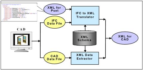
Figure 3: Generation of XML file from CAD or IFC file (Qizhen et al., 2001)
There are known issues with translating IFC to ifcXML, as this process is not one-to-one mapping and information can be lost during the translation. The issues however are insignificant and can be addressed by a system accommodating new terms and relationships as being developed and incorporated in the ifcXML schema (Cheng et al., 2003).
When it comes to the size of file, ifcXML is normally two to six times larger than IFC file. That makes the ifcXML files very large, becoming unsuitable for exchange over the Web in their entirety. Due to this reason, methods have been developed to export and import only portions of the file, i.e. these that undergone change (Qizhen et al., 2001).
Similarly to IFC, ifcXML supports AEC lifecycle project information including all the specialist disciplines such as architecture, structural, building services, construction, and facility management. IfcXML not only models a basic building information, like the geometry and product data, it also models data from various project management applications such as process and activity information, including programme/schedule and cost or cash-flow (Cheng et al., 2003).
With XML representing IFC data, more applications are able to access the schema representing the built environment. XML, with its broader range of supporting utilities and database implementations, is the base for many eCommerce and Web services solutions, which are also supported by Web browsers, making the information accessible on a wide range of hardware including mobile devices. IfcXML is taking benefit of the internationally accepted AEC standard and has been widely tested in several domains (International Alliance for Interoperability, 2007).
There are other domain-specific schemas in existence that may be mapped to XML. According to International Alliance for Interoperability (2007) the AEC industry is committed to use ifcXML and wanting to argument it with other XML schemas to enable business or process areas that are not yet covered by the IFC model. The example is aecXML, which definition is being submitted to the buildingSMART, formerly known as IAI (The International Alliance for Interoperability), for consideration in IFC model extensions. For the similar reasons, the place was found for agcXML being the AGC (The Associated General Contractors of America) construction-related data, and gbXML used for green sustainable buildings (Sabol, 2008)
2.4 Conclusions
Widespread adoption of digital technology is visibly affecting the AEC industry with introduction of systems that require redefinition of the traditional, proved and intuitive business processes, articulation of peoples communication and its tools, assuring that the new technologies work seamlessly with each other and well interface with the people involved. People, who are often caught in the middle, are often left with no alternative but to rapidly shift their mind-sets from individual project delivery to developing self-interest of the common good, despite of their adopted and established way of working. Adding the parallel exercise of transiting from the conventional and manual pen/paper tools and verbal communication, such adoption of the information technology may not be comfortable and easily achievable. Continuous education, and most impotently self-desire, may be only alternatives for the successful adoption of the AEC modern technologies.
With the complexity of the AEC projects today, coupled with complex technologies rapidly entering the industry, the members of distributed interdisciplinary teams would not succeed without implementing alternative methods and tools of project delivery. Such technology and process advances have been captured by BIM, its power of information management, its concept of integrated design, and finally its desire of interoperable process for project delivery. BIM in turn introduces vast amount of specialist software applications for the build teams to extend these into collaborative projects. Such software applications often adopt state-of-the-art parametric modeling, specialist calculations, and analyses. Standalone proprietary software solutions brought into BIM not necessary communicate to each other; significantly contributing to project deficiencies and errors.
The difficulty in an immediate fix of interoperability issues falls with the lack of agreed methods for testing; Therefore, any investigation towards addressing interoperability needs to be settled with trial-and error approaches like prototyping and integrity evaluation of models on a case-by-case basis. Such work is mostly left to the project stakeholders, mainly architects who are the heaviest users of BIM technology. They are exposed to coping with interrelations between numerous software solutions employed in BIM. With complexity of projects today and the amount of diversified software applications utilised, the team players will most certainly experience challenges in resolving interoperability issues. This is in light of having no prior experience and due to lack of published evidence of existing companies which would undertake such activities. Departing from traditional highly linear and manual process of project delivery by joining forces of IPD would make this process even more difficult.
Software programs utilised in BIM may be equipped with reasonable translators, yet may not necessarily meet demands of highly sophisticated project data models and the stringent information exchange requirements. Fortunately, the translators are not the sole interoperability alternative, with the wide range of different methodologies, software systems, and technologies in existence, such as middleware, proprietary exchange file formats, standards and open-specification data models, project model servers, Web services, and semantic Web applications.
Historically, the desired characteristics of products and services, including their quality, reliability, efficiency and interchangeability, have been ensured by standards. A number of standards organisations are striving towards making products and services interoperable. For the purpose of this research, this is lead by initiatives or standards such as ISO, STEP, CIS/2, IFD, IDM, XML and IFC, being the solutions specifically intended for the AEC industry. IFC is the de facto format for BIM models worldwide, and has been taken forward for testing of interoperability solutions in the later chapters. Well defined IFC Specification schema, composed of entities, attributes and relationships between entities, effectively defines the way by which the population of these entities and relationships needs to be represented. IFC offers a facility to enhance flexibility and extensibility of its Object Model. IFC Views, being a subset of the IFC schema, allow for formation of domain-specific data specifications for a particular model exchange scenario. By translating IFC source files into XML file format it is possible to employ another specification called ifcXML. Along with other domain-specific schemas that may be mapped to XML, such as aecXML, agcXML and gbXML, ifcXML is being interfaced with XML to enable business or process areas that are not yet covered by IFC model. Despite certain reservations to IFC, i.e. that the standards is the lowest common denominator, having visible issue with round-tripping, and imperfect certification process, IFC remains the only well-developed, non-proprietary and public data model for the AEC industry, existing today.
IFC may not necessary be a sole standard utilised in a single BIM project. It may be employed in a partnership with other industry-standard product models or electronic data exchange formats that suit a particular domain.
Identifying the project-specific interoperability issues remains difficult without leaning towards areas of generalisation. Fifteen different software applications had been utilised in this Research Report to address this issue. Such approach most likely exceeds requirements of even the most demanding projects, yet could be only used for illustrative purposes, and rarely as project-specific solution. Any interoperability issue could be only addressed if identified with a prior definition of investigative methods leading to disclosing such an issue. Software vendors play substantial role in addressing interoperability issues, as it is to their interest to advance the software programs in response to the market and to win the customers.
With the initial knowledge of the AEC industry and the review of over one hundred and fifty references, the work in this chapter provides numerous answers, but yet opens a series of new issues which require further work and alternative methods of investigation, such as model prototype building, sampling and testing. Such items have been captured in Section 3.3 Research Questions, and include, but are not limited to interoperability specific issues and methods of disclosing them, compliance criteria intended for model integrity checks, software evaluation against interoperability standards, interoperability investigation against efficiency and accuracy of information retrieval, interoperability quantification, key characteristic of acceptable standards, maturity of interoperability standards, reliability of such standards with identification of the areas of improvement, and interoperability obstacles.
This chapter expands on the aims of the research and details the research questions. A total of ten questions or rather groupings of questions were identified, all being based upon the aims of the research. The research anticipates generating the answers or recommendations to the questions listed. The research limitations and hypotheses are also listed in the chapter for later consideration.
3.1 Introduction
The research questions listed in this Chapter have allowed for setting out the aims of the research and its limitations. The principal objective of this section was to address the items discussed in the literature review that require further investigation, as illustrated in Chapter 2: Review of Previous Work. The literature reviews unanswered topics have been translated into the research questions and are listed in Section 3.3. They refer to the areas such as identifying effective methods of disclosing interoperability issues and examination of compliance criteria that had been established for model integrity checks. The questions further capture the issue of software evaluation against interoperability standards and interoperability investigation against efficiency and accuracy of information retrieval. They further bring the subject of interoperability issues quantification, followed by the key characteristic of the acceptable standards, raising the issue of maturity of such standards. The series of questions ends on looking into reliability of standards with identification of areas of improvement, interoperability obstacles, and how these could be addressed.
3.2 Aims
The primary aim of this Research Report was to analyse the current state of interoperability among architecture, engineering, and construction software applications utilised in Building Information Modeling and implication of standards in this area. The analyses have been instrumented by examining industry common software standards in order to identify specific issues and to make recommendations leading to improving interdisciplinary collaboration in BIM.
In the background, the mission of the research was to promote innovation in the AEC industry. It was also to promote competitiveness among AEC software application developers who should progress with addressing the interoperability issues, but without putting restrictions to continuous advances of technology in their software applications.
3.3 Research Questions
The questions are based upon the aims of the research outlined in Section 3.2 and are listed below. They are placed in a sequential order corresponding with the structure of the investigation adopted in this research paper.
Research Question 1
It is commonly known that interoperability issues do exist. What methods should be adopted to disclose these issues? What are the issues specifically?
Research Question 2
What criteria should be in place to examine interoperability in BIM and to check content of the files utilised, specifically IFC files, not only from the perspective of the model geometry, but its attributes and Psets? How to establish that the model is compliant and integral, and with no data loss, when compared with the one generated using original model authoring applications? What does compliant actually mean?
Research Question 3
What is the source of interoperability issues: the software or the standards? Will IFC files exported from original authoring applications be compatible in terms of their geometry and properties they transmit? Are the software vendors in a position to catch-up with the advances of standards development?
Research Question 4
Is there a connection between interoperability and effective extraction of data from a system? How interoperability helps in an effective retrieval of information from among the vast amount of data stored on a system?
Research Question 5
Why there is a value in interoperability, why it is important? How interoperability issues affect interdisciplinary collaboration in BIM? Can the impact of the interoperability issues be quantified?
Research Question 6
What does it mean to have a good standard?
Research Question 7
Is IFC mature enough to be a standard? What is the history of its development, and what is being planned for the future? Does IFC answer current issues with interoperability? How expressive or expansible IFC is? Does IFC provide a facility for a standard way of dealing with non-standard extensions?
Research Question 8
Is interoperability reliable? Is there such a thing like IFC-compliant BIM? Can the data exchanges among the project stakeholders be trusted? How to control it?
Research Question 9
Is interoperability in BIM affected in any way by interrelations between members of the distributed team? What recommendations could be made to improve interoperability in light of interdisciplinary collaboration?
Research Question 10
What invites interoperability issues? What are the obstacles, and how to overcome these?
3.4 Research Limitations
The key limitation of the Research Report is the chosen approach to prototyping and interoperability testing. With the vast amount of software applications and management techniques in place, a view needed to be taken what software packages, work flows, and testing regimes such type of research should be subject to.
A view was taken early in the project on the specific areas which should not be covered by the research. Although the project includes elements of AEC software evaluation from the perspective of interoperability, it never intended to be a software review exercise. The project has not concentrated on areas outside of Building Information Modeling and targeted specifically parametric models and their object attributes. For this reason, the research has omitted instances of files that cannot be converted to standards like IFC or ifcXML. Interoperability among 2D CAD files has been only highlighted for illustrative purposes and not pursued throughout the Research Report. The project has also omitted modeling that is lacking automation functionality, being for example interactive schedules and modification of floor plans that automatically update the model elevations, sections, and details.
The view was taken that utilising a commercial IFC model server in prototyping, testing, and analyses was beyond the scope of this paper. Therefore, the substitute was found by utilising Solibri Model Checker as the model repository. IFC model servers are discussed in Section 4.2 Collecting Data.
The research has not attempted to resolve issues related to flaws of the software, otherwise known as bugs. It needs to be also recognised that the projects objective has not been necessarily to resolve BIM related interoperability issues, but to highlight them, suggest the resolutions when possible, and attempt to use some of the finding as a post-Research Report challenge as seen in Section 6.2 For the Future.
3.5 Hypotheses
Upon commencement of the research it is intended that the following hypotheses are validated:
Hypothesis 1
Success of resolving interoperability issues depends on methods employed to discover such issues.
Hypothesis 2
There are known issues with interoperability and it is possible that such issues be specifically identified and named.
Hypothesis 3
IFC, as well as ifcXML, are sufficiently mature to be adopted in projects utilising BIM. Teams are prepared to undertake a challenge of interdisciplinary collaboration while submerging in BIM.
3.6 Conclusions
The aim of this research was to analyse the current state of interoperability in the AEC industry while utilising BIM, and to evaluate implication of standards for the industry-related software applications. A number of research questions, which are based upon the aims of the research, were identified during the literature review. The questions, with a wide selection of topics, were subsequently listed and put forward for further investigation and analyses. Research limitations were realised, ranging from the prototyping approach, software issues, and workflows, to BIM, IFC/ifcXML, 2D, model servers, and items that could be a subject to future research. Finally, the hypotheses had been spelled-out, and these specifically refer to methods used in interoperability evaluations, interoperability specifics and its limitations, and adoption of standards by interdisciplinary teams.
The work in this chapter provides detailed description of investigation methods and illustrates how the data was collected. It graphically introduces model prototyping and testing methodologies.
4.1 Introduction / General Approach
The choice of research methods used in this Research Report was to assure full answers to the questions raised in Section 3.3 Research Questions. The attention was paid in this chapter to the type of data needed, research strategy adopted, data source, methods of data collection, and methods of data analysis (Mador, 2008).
The research design chosen for the Research Report constitutes mainly of quantitative methods; however, it does contain an element of qualitative research. The research could be therefore categorised as a mixed strategy, popular with business researchers (Mador, 2008). The choice of the research design, whether quantitative or qualitative, was due to variations in a nature of the research questions.
The quantitative strategy was adopted to assure that the concepts are measured by data collection and analyses, instead of being obtained as a meanings from individuals (Mador, 2008). Data collection and the analyses begun by the software implementation; a prototype was developed to test the modeling concepts and the interoperability of the extended IFC models (Yang, 2003). The testing was found essential, as the current translators to IFC and ifcXML are not without deficiencies. The type of the data needed for this research was to meet the established requirements for testing and analyses. This data generally comprised of elements of the prototype model, whether its geometric form viewed with IFC viewers or CAD software, or its file-structure form viewed with tree viewers or analysers. The data source had to be justified and appropriate, and constituted Authors prototype models and the secondary sources referenced in the text. This had been found necessary, as it was felt that the literature review needed to be backed up by the data generated from an actual model to better illustrate the issue and for verification purposes. The methods of data collection needed to be efficient due to the volume of the work undertaken and, by default, were driven by capabilities of the individual software packages utilised in the research. The methods mainly involved extracting relevant data or information in various forms, as required for analysis. The intention was that methods of analysing data would be performed with a set of rules in mind and would comply with the industry recommendations obtained through the literature review and the software evaluation. Such set of rules involved adoption of standards like IFC and ifcXML, and has mainly concentrated on the visual comparison of either: model geometry, its code, or inspection or confirmation of the models entity attributes.
The qualitative element of the research pertained mostly to logistics and organisational context of the Research Report. It reported on the opinions, views or internal perceptions of Author or other people (Mador, 2008). Both, data and concepts to analyse this data were identified through the literature review. The research had also elements of action-research. This is due to adopting a number of the characteristics such as fact-finding to practical problem solving, involving practitioners and laymen by researching their work as referenced in the Research Report, collaborating with industry professionals including scholars and software vendors, and diagnosing the problem in a specific context in attempt to solve it (Burns, 2000).
The mix strategies adopted in this Research Report occasionally introduced elements of triangulation process, where judgements were taken regarding the data sources, data collection types, and appropriateness of analysis types for the most effective delivery of research (Mador, 2008).
The limitations noted in Section 3.4 Research Limitations mostly relate to quantitative method, the method that prevails in the Research Report.
The described above quantitative methods strictly provide for visual inspection of the models geometry with some examination of other model information such as individual entities and their attributes. According to the National Institute of Standards and Technology (2010a), typical method for inspecting the content of a product model, which may be represented by IFC files, is to visualise it with an IFC viewer, opening it in CAD software, or to view the file structure with a tree viewer. These methods however, provide only a visual confirmation of the model and are intended for inspecting the individual entity attributes. As further advised by the National Institute of Standards and Technology (2010a), there are no other methods currently in place to evaluate the content of a model and its IFC file in terms of providing accurate determination, comparison, or measures.
The research contains elements of AEC software review. This is strictly to decide on the software applications that should be utilised in the Research Report. This is also to examine the software key interoperability features in preparation for testing.
The research approach only partially relies of the secondary sources, being the published reports. Each time such the secondary source was used, the corresponding method of data collection and the limitations are explained in the text.
Finally a substantial number of test files were generated, as part of the data collection and in attempt to test the interoperability. Each time such primary data was collected, details of the sampling procedures were also provided, along with the performed analyses including, where applicable, statistical techniques. The individual test results were collected in a tabular form and summarised.
Both, References and Appendix 2 - Bibliography material, was collated, organised, and managed from Thomason Reuters Corporation (2010) EndNote bibliographic database solution. Conventions for citing the information sources in the text of the Research Report and in the References list or Appendix 2 - Bibliography are based on Pears and Shields (2008). The assistance in writing the Research Report was obtained from the Kingston University London, Faculty of Business and Law, Business Information Technology MSc course Director, Stewart Fitzgerald, the course Supervisor, Phil Molyneux, and the number of the course faculty staff lecturing through the period of the study. The assistance was also received from Bovis Lend Lease Limited (BLL), as well as Lend Lease Corporation (LL) whose BLL is a wholly owned subsidiary. LL and BLL contribution was through recognising the value of the course, relevance to its core businesses, and through numerous opportunities to discuss the Research Report topics and the related issues with LL and BLL staff. Further assistance was provided by Lend Lease consultants who kindly agreed that their 2-dimensional CAD drawings are used by Author to generate the corresponding 3D model files utilised for the purpose of data collection, testing and analyses. Such consultants are the joint venture of architectural practices Patel Taylor and Bligh Voller Nield, and civil and structural practice of Robert Bird Group, along with the building services consultancy Wallace Whittle. Finally, the insights for this Research Report were provided by Collaborative Modeling Ltd.
4.2 Collecting Data
The initiation of the prototype model production needed to be associated with deciding which IFC2x release of the specification should be utilised in the project, whether Edition 2 or 3. The decision had to consider the project stakeholders involved, whether they had compatible software enabling them to read the chosen file version (Graphisoft US Inc., 2009). In the end, the decision was made to select the newer Edition 3, hence release IFC2x3 was utilised, which according to buildingSMART (2009b) was released in 2005, and it is already well known to the software vendors. Each vendor of the software utilised in this research promotes its product with the release IFC2x3. The IFC2x4 release, as of May 2010, is a candidate only, and therefore has not been considered in the research.
The process of developing the prototype involved project stakeholders identified in sub-section Project Stakeholders and the Project Approach included in Section 2.2 Literature Review. The process commenced with Architects-Concept Designs scheme, referred to in the text as Start-Up Model leading to 3D parametric model, leading to 3D parametric modeling. Architects-Concept Design utilised their original modeling authoring application in the production of the initial model. The ArchiCAD 2D representation of the 3D model is shown in Figure 4, Figure 5, and Figure 6.
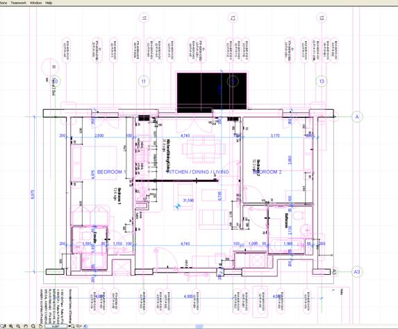
Figure 4: Start-Up Model (native ArchiCAD 3D model plan view opened in ArchiCAD) with 2D overlay
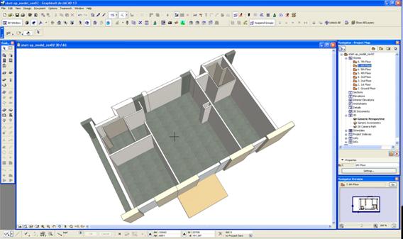
Figure 5: Start-Up Model of an apartment - native ArchiCAD file opened ArchiCAD
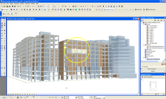
Figure 6: Start-Up Model in a context of the city block (native ArchiCAD 3D model opened in ArchiCAD)
Following the above, Start-Up Model was saved to IFC2x3 file format. Details pertaining to the software settings used while saving the file to IFC are illustrated in Appendix 1 - Supporting Documents under Section 2.1 Saving Start-Up Model to IFC2x3. The IFC file was consequently forwarded for testing.
Start-Up Models IFC file was first placed on a model server. Many model server solutions are in existence today, and its number is growing due to the industry increased interest in developing methods and tools for interoperability (Young et al., 2007). Companies like Secom, Eurostep, EPM Technology, and Oracle currently offer such building model repositories.
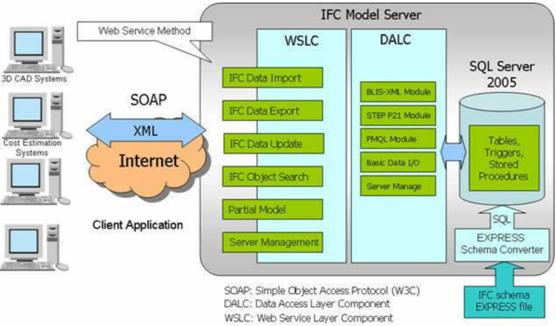
Figure 7: Sample model server - Secom IFC Model Server architecture (Adachi, 2010)
Due to the nature of this research project, being after all the student undertaking, the view was taken that utilising and financially supporting a commercial IFC model server in the prototyping, testing and analyses was beyond the scope of this paper. To substitute the model server, Solibri Model Checker was utilised as the model repository instead.
Once Start-Up Model was placed on model server it made itself available to the remaining consultancy disciplines, such as Civil & Structural Engineers, Building Services Engineers, and Envelope Designers for further development of the design and testing as disused in Chapter 5.
4.5 Conclusions
The research design in this Research Report is classified as a mixed strategy with the prevailing element of quantitative methods and sporadic qualitative approaches. The quantitative strategy have been applied to modeling and the related data collection and analyses. The individual test results have been tabulated, summarised, and evaluated. Modeling and testing has been found essential, as the current file translators are not entirely reliable and do not provide a facility of rigorous identification of interoperability issues resulted with the file conversions and exchange. These methods have been however, limited to the model geometry, its entities, and the attributes, as there are no other methods currently in place to provide more accurate assessment of models. The qualitative portion of the research strategy has been only related to peoples opinions and perceptions. Elements of action-research have been identified within the collaboration process involving the industry professionals while producing this research report. A mix of strategies implemented in this Research Report occasionally introduced elements of a triangulation process, taking judgements regarding the data, its analyses, and the analyses appropriateness. Published reports had also contributed to data collection. The general approach to this Research Report was assisted by the Kingston University faculty.
The process of collecting data was closely linked with the adoption of IFC2x3. It involved a set of example stakeholders, lead by architects, with the developed by them Start-Up-Model. While understanding and appreciating value of a model server, the decision was made to substitute it with another model repository, Solibri Model Checker. This still provided for the desired functionality of making the model available to the remaining members of the distributed project team for interdisciplinary collaboration, prototyping, testing and analysing interoperability, and interoperability evaluation.
This chapter is the core of the research problem and comprehensively addresses the research questions involving the series of digital model-building exercises and testing. It commences with unfolding interoperability issues and transits into rich illustration of interoperability testing through analyses of workflow scenarios utilising several BIM computer applications. The series of background and finding areas lead to the answers of the research questions.
Enormous time and effort was put into setting the criteria for interoperability evaluation, assembling and testing over fifty interdisciplinary models, employing fifteen different software applications, arriving with conclusions, and evaluating the resulted interoperability issues.
5.1 Introduction: Unfolding Interoperability Issues
This sub-section addresses the Research Question 1 by establishing the methods needed to disclose interoperability issues and by looking into the specifics of such issues.
Further to the review of interoperability standards and in light of general concern over the issues related with the exchange of files among the project stakeholders, the question remains what are the issues specifically. One of the immediate issues needing attention was the structure of the interdisciplinary team and the way the individual, distributed members would collaborate. Prior to commencement of the digital prototypes and the testing, it was found necessary to establish a workflow intended for production of the model and the effective exchange of project information. The workflow was based on the principle of collaborative engagement of the project stakeholders, each importing the information or data from model server, revising it or producing additional information, followed by exporting it back to the server, as illustrated in Figure 8.
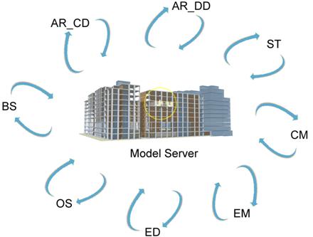
Figure 8: Collaborative data exchange scenario by interdisciplinary team (refer to Table 1 for abbreviations)
In the first instance, the chosen workflow needed to be appropriate to assure that it reflects each companys agreed approach to information production with collaboration in mind. The example of the workflow, similar to the one adopted in this research work, is shown in Figure 9. The workflow applies to all the disciplines, but extends its activities of architects and building services engineers shown in the diagram to the remaining disciplines involved in the collaborative process of information exchange, such as civil & structural engineers, envelope designers, etc.

Figure 9: Interdisciplinary collaboration workflow process map (Weise et al., no year)
In order to fully answer the subject research question it was necessary to examine BIM process, the modeling involved, the computer applications utilised, and the applicable interoperability standards in use. This was instrumented by prototyping and testing methods. Having already identified some of the IFCs drawbacks, the conformance testing has been found essential.
Before testing could commence, a set of criteria was established that could be used in the conformance checks and to define perimeters for compliant files, as discussed in Section 5.2 Setting Criteria.
The testing begun by opening Start-Up Model that was described in Section 4.2 Collecting Data, with and without the layer containing 2D information, in the IFC viewers, such as Solibri Model Viewer, DDS-CAD Viewer, and Nemetschek IFC Viewer, as well by opening it in the software applications used by the project stakeholders, being Employer, Architects-Concept Design, Architects-Detail Design, Civil & Structural Engineers, Building Services Engineers, Envelope Designers, Contractors, and Others. This was illustrated in Section 5.3 Assembling and Testing Interdisciplinary Model. The concept behind testing was to observe the behaviour of design characteristics of the model objects while being extracted from the model and transformed for re-use, meaning the use in other discipline specific computer applications (Yang, 2003).
5.2 Setting Criteria and Commencing Tests
This sub-section provided further answers to the Research Question 1 regarding the identification of specific interoperability issues. It also addressed the Research Question 2 pertaining to selection of criteria used in modeling conformance checks and to define compliant files. The answers, along with the knowledge gained through literature review, constituted the core findings of this research and were concentrated on two key issues, (1) prototype model testing and inspecting, along with establishing criteria for examination of interoperability issues, and (2) identification of specific issues emerged through the tests and conformance inspections, as well as evaluation of interoperability.
For the purpose of establishing the interoperability evaluation criteria, it was necessary to instrument an initial examination of the model. The examination begun with a visual inspection of the 3D file containing 2D information, saved with 2D Elements selected in ArchiCAD IFC2x Export settings, by opening it in IFC viewers. This has exhibited a number of inconsistencies and elements of file corruption, particularly with 2D. This was surprising, as 2D interoperability issues were the least expected, bearing in mind that according to Summers (2008), the first traces of CAD and 2D were seen in 1957, over fifty years ago. It became clear that IFC is not appropriate for exchange of 2D files used in interdisciplinary collaboration. The IFC export and import settings[8] may give misleading message of IFCs full range of functionality to handle 2D files. Only after referring to the reference guide by Graphisoft US Inc. (2009) it becomes clear that such functionality is limited to 2D vector elements like text, line, arc/circle, polyline and fills, but not to enhanced automatic options offered by the software, such as auto-dimensioning, elevation markers, cross-section markers, doors and window markers, etc. Due to these factors, the view was taken that, until the time IFC facilitates 2D, the 2D should be excluded from IFC exchange, and therefore from any related interoperability checks, and instead may be captured in its original authoring application format or addressed with 2D exchange standard like the popular in AEC proprietary exchange format DXF. Depending on the project requirements and the workflow, it may be not be necessary to exchange the 2D non-parametric model information after all. The 2D interoperability analyses to date had been placed under Appendix 1 - Supporting Documents under Section 2.2 2D Information within 3D Model, and have been no longer pursued in the research.
From this point, the examination has concentrated on parametric models only, and continued with analysing Start-Up Model 3D file and inspecting its individual entities, as well as the entity attributes. The assembled Start-Up Model included three IFC entities, (1) IfcColumn, (2) IfcSlab, and (3) IfcWall, as defined by ArchiCAD. IFC File Analyzer was first utilised to view the content of Start-Up Model IFC file. IFC File Analyzer is a conformance assessment tool and was used to evaluate the coverage of IFC product data model files. This software tool provided a framework with the functionality of collecting meta-data of values used in IFC files. It also provided a platform for evaluating characteristics of data that was important in determining and evaluating information in the files (The National Institute of Standards and Technology, 2010a).
The MS Excel spreadsheet generated by IFC File Analyzer disclosed a number of standard and non-standard entities and their attributes, including IFC Pset names. The non-standard Pset names, meaning the names of the entities that include non-standard Psets, were highlighted in the spreadsheet. Only the entities listed in rows 8 to 11 inclusive are standard, as illustrated in Figure 10. Close attention should be paid to no-standard Psets, as these may not be interoperable across all the software applications employed in BIM.
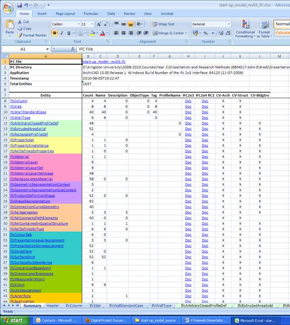
Figure 10: Start-Up Model IFC file opened with IFC File Analyzer (partial)
The attention should be drawn to the new entity name IfcWallStandardCase, which appears on the spreadsheet in the line item 10. This entity still represents the wall, but is the subtype of IfcWall. The IFC specification provides two entities for wall occurrences, IfcWall and IfcWallStandardCase. IfcWall is used for all occurrences of wall, i.e. walls which are non-vertical or having variable thicknesses. In contrast, the subset type IfcWallStandardCase is used for standard vertical wall of uniform thickness throughout its height (buildingSMART, 2010c). The entities used for the initial visual examination comprised of standard Psets only. The complete copy of the spreadsheet is included for reference in Appendix 1 - Supporting Documents under Section 2.3 IFC File Analyzer: Spreadsheet of Start-Up Model IFC File.
Based on the initial examination of the model, a number of integrity checks criteria had been established, and grouped in the eight distinct areas: (1) element geometry that refers specifically to accuracy of parametric model geometry, (2) element relative position that relates to accuracy of elements of the model in terms of the relation to each other, (3) element colour coding integrity checks that refers to inconsistencies in colour coding of elements carrying similar or identical attributes and properties, (4) entity and element count that concentrates of verification of entity and element quantities and completeness, (5) schedule of values (spot-check) that addresses accuracy of selected attributes and property values, (6) entity attributes and (7) entity Psets examination that verifies whether all the entity attributes and Property Sets are accurately listed, and finally completeness checks of (8) model tree-structure. Each of the examined areas had been summarised in the individual tables below and coded with the following icons for illustrative purposes:
![]() no issues found
no issues found
![]() issues identified and
described
issues identified and
described
![]() not examined
not examined
Model integrity checks were performed following the established criteria above. The examination started by visualising models with IFC viewers and by processing the files in a number of proprietary software applications. This followed with general visual inspection of individual model elements examining their geometry, relative position, and colour coding. General check on quantity of entities and the associated model elements took also place. As illustrated in Figure 10, the model comprised of three entities, IfcColumn, IfcSlab, and IfcWallStandardCase, each having four, eight, and forty elements respectively A spot-check was performed on the individual IFC entity attributes, such as Name, Description, Type, Material, and GUID[9]. The examination also included additional parameters assigned to IFC entities, such as properties contained within each entity Pset. Finally, the examination of the selected files included viewing the file structure with a tree viewer, code analyses, and modifications to IFC or ifcXML code to illustrate the issues.
The initial examination approach was to maximise the amount of software applications utilised in BIM, and due to volume restrictions of this research document the overview of interoperability issues across the elements of the models was initially generalised. The interoperability specific issues were examined in depth on a case-by-case basis in later paragraphs of this Research Report. The findings have concentrated mainly on non-compliances in the information exchange process.
This visual examination of Start-Up Model has employed Solibri Model Viewer. The screenshots are shown in Figure 11, with finding summarised in Table 3.
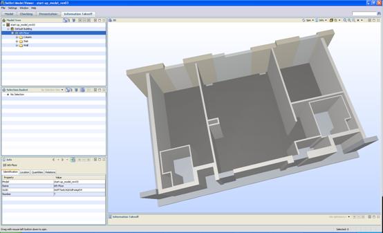
Figure 11: IFC Start-Up Model opened in Solibri Model Viewer
Table 3: Start-Up Model - Solibri Model Viewer examination
|
Element geometry |
|
|
|
Element relative position |
|
|
|
Element colour coding |
|
|
|
Entity and element count |
|
|
|
Schedule of values (spot-check) |
|
|
|
Entity attributes |
|
Description missing |
|
Entity property sets (entity Psets) |
|
|
|
Model tree-structure |
|
|
The only area of a non-compliance that emerged during the visual examination above was the missing value of the entity attribute named Description. This would appear as a minor inconsistency; however, it was expected that translation would accurately inform of all entity attributes without exemptions.
The examination continued with viewing the model in DDS-CAD Viewer. The screenshots are shown in Figure 12 and finding are summarised in Table 3.
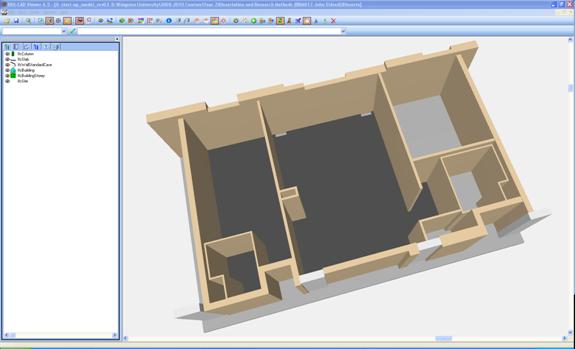
Figure 12: IFC Start-Up Model opened in DDS-CAD Viewer
Table 4: Start-Up Model - DDS-CAD Viewer examination
|
Element geometry |
|
|
|
Element relative position |
|
|
|
Element colour coding |
|
Inconsistant |
|
Entity and element count |
|
|
|
Schedule of values (spot-check) |
|
|
|
Entity attributes |
|
|
|
Entity property sets (entity Psets) |
|
|
|
Model tree-structure |
|
|
The key discrepancy from the native model was the colour differentiation between the identical floor materials for Bedroom 1 and Bedroom 2 flooring, suggesting different specification of the material. Similarly, flooring in both Bathrooms was of the identical specification, yet being shown in contrasting colours.
The next free viewer selected for checking Start-Up Model was Nemetschek IFC Viewer, as illustrated in Figure 13 and the corresponding Table 5.
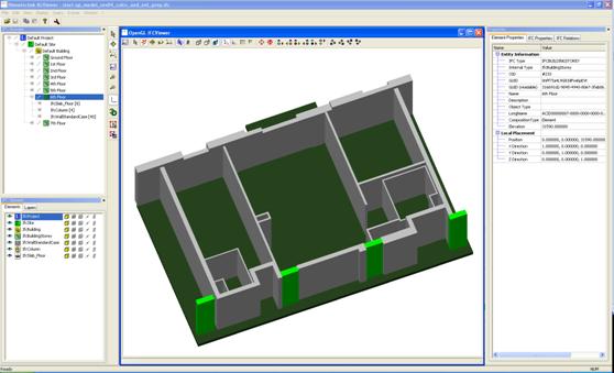
Figure 13: IFC Start-Up Model opened in Nemetschek IFC Viewer
Table 5: Start-Up Model - Nemetschek IFC Viewer examination
|
Element geometry |
|
|
|
Element relative position |
|
|
|
Element colour coding |
|
|
|
Entity and element count |
|
|
|
Schedule of values (spot-check) |
|
|
|
Entity attributes |
|
|
|
Entity property sets (entity Psets) |
|
|
|
Model tree-structure |
|
|
No issued were found while performing the visual confirmation.
The last free viewer utilised in analyses was IFC Engine. The screenshots are shown in Figure 14 and finding summarised in Table 6.
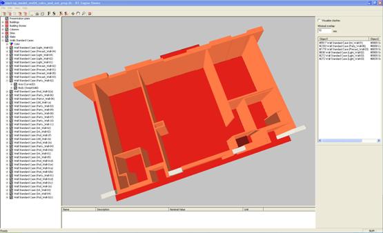
Figure 14: IFC Start-Up Model opened in IFC Engine Viewer
Table 6: Start-Up Model - IFC Engine Viewer examination
|
Element geometry |
|
|
|
Element relative position |
|
|
|
Element colour coding |
|
Inconsistant |
|
Entity and element count |
|
|
|
Schedule of values (spot-check) |
|
|
|
Entity attributes |
|
Description missing |
|
Entity property sets (entity Psets) |
|
|
|
Model tree-structure |
|
|
Similarly to Solibri IFC Viewer, IFC Engine Viewer did not show the value of the Entity Attribute named Description. The other discrepancy found was the contrasting colour of Utility Cupboard floor, as shown in the model in dark burgundy. The flooring specification of the room was identical to Bathrooms, and the differentiation in the colour suggested the contrary.
Following the series of examinations using free IFC viewers, the check was performed with ArchiCAD, the software application used for the purpose of this research paper to generate Start-Up Model. The model screenshot is shown in Figure 15 and the summary finings placed in Table 7.
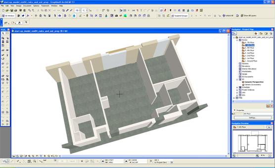
Figure 15: IFC Start-Up Model opened in ArchiCAD
Table 7: Start-Up Model - ArchiCAD examination
|
Element geometry |
|
|
|
Element relative position |
|
Issue with Extended Properties settings[10] |
|
Element colour coding |
|
|
|
Entity and element count |
|
|
|
Schedule of values (spot-check) |
|
|
|
Entity attributes |
|
|
|
Entity property sets (entity Psets) |
|
|
|
Model tree-structure |
|
|
No inconsistencies were initially found during the visual examination of IFC Start-Up Model opened in ArchiCAD, but some emerged in later testing.
The next software package used for evaluation of IFC Start-Up Model was Digital Project. The screenshot of the model and the model tree structure is shown in Figure 16. The findings are summarised in Table 8.
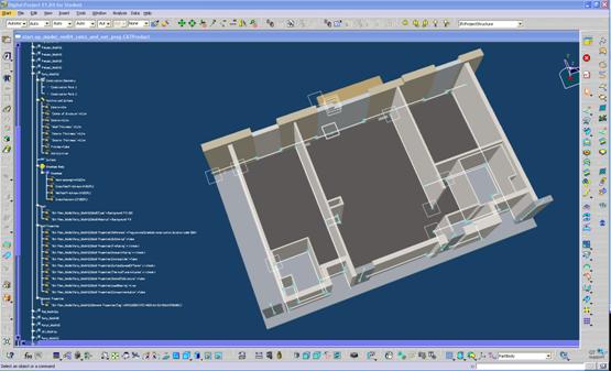
Figure 16: IFC Start-Up Model opened in Digital Project
Table 8: Start-Up Model - Digital Project
|
Element geometry |
|
|
|
Element relative position |
|
|
|
Element colour coding |
|
|
|
Entity and element count |
|
|
|
Schedule of values (spot-check) |
|
|
|
Entity attributes |
|
Description not visible |
|
Entity property sets (entity Psets) |
|
Some Psets not visible |
|
Model tree-structure |
|
|
Digital Project did not show the value of the Entity Attribute named Description in its model tree. Additionally, the model tree showed only one of the three Psets with assigned customised property values, omitting Pset_FireRatingProperties (with the value of 60 minutes) and Pset_QuantityTakeOff (with the value of VP Party Wall 0002).
The examination followed with Vectorworks as illustrated in Figure 17 and Table 9, summarised below.
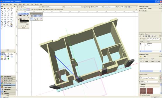
Figure 17: IFC Start-Up Model opened in Vectorworks
Table 9: Start-Up Model - Vectorworks
|
Element geometry |
|
|
|
Element relative position |
|
|
|
Element colour coding |
|
|
|
Entity and element count |
|
|
|
Schedule of values (spot-check) |
|
Not visible |
|
Entity attributes |
|
|
|
Entity property sets (entity Psets) |
|
Missing |
|
Model tree-structure |
|
Examination not performed |
It was not possible to obtain a schedule of values in Vectorworks that would allow for verification of element properties. Some Entity Psets were not listed in Vectorworks IFC Data palette, and shown no values.
The visual comparison of the model and its parameters continued with MicroStation software application. The model is illustrated in the screenshot in Figure 18. The findings are captured in Table 10.
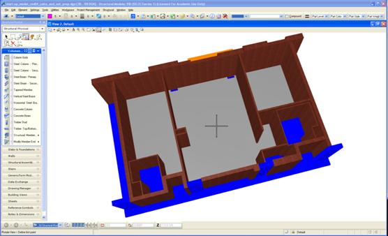
Figure 18: IFC Start-Up Model opened in MicroStation
Table 10: Start-Up Model - MicroStation
|
Element geometry |
|
|
|
Element relative position |
|
|
|
Element colour coding |
|
|
|
Entity and element count |
|
Incomplete |
|
Schedule of values (spot-check) |
|
|
|
Entity attributes |
|
Not visible |
|
Entity property sets (entity Psets) |
|
Not visible |
|
Model tree-structure |
|
Examination not performed |
The entity listing was incomplete, missing IfcColumn. Entity attributes, as well as Entity Psets, were not listed in the Element Information.
Examination of the IFC file opened in Revit shown in Figure 19 resulted with a number of issues as summarised in Table 11.
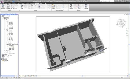
Figure 19: IFC Start-Up Model opened in Revit
Table 11: Start-Up Model - Revit
|
Element geometry |
|
|
|
Element relative position |
|
|
|
Element colour coding |
|
|
|
Entity and element count |
|
Examination not performed |
|
Schedule of values (spot-check) |
|
Inconsistencies |
|
Entity attributes |
|
Inconsistencies |
|
Entity property sets (entity Psets) |
|
Not visible |
|
Model tree-structure |
|
Examination not performed |
Schedule of values check disclosed that only some of the values were shown in Revit Instance Properties window and the values shown were not entirely accurate. In one particular example the height, the area, and the volume of an element was accurate, but the length was incorrect with the discrepancy of approximately 3%. Entity attribute Name incorrectly identified its element, as it gave the name of some other element in the model. Psets were not listed in Revit Instance Properties window.
The Constructor model examination followed the steps undertaken in the previous software application examination and is illustrated in the screenshot in Figure 20 and Table 12 with the description below.

Figure 20: IFC Start-Up Model opened in Constructor
Table 12: Start-Up Model - Constructor
|
Element geometry |
|
Some corrupted |
|
Element relative position |
|
Affected by element geometry |
|
Element colour coding |
|
|
|
Entity and element count |
|
|
|
Schedule of values (spot-check) |
|
Errors |
|
Entity attributes |
|
|
|
Entity property sets (entity Psets) |
|
Some missing |
|
Model tree-structure |
|
Examination not performed |
Geometry of the model elements were found corrupted. The length of the walls was increased, affecting the relationship of the walls with the adjacent elements. This affected the quantities as shown on the schedule of values. Entity Psets were shown on Constructors Element Selection Setting palette, but some of the Psets were missing.
The examination of the IFC Start-Up Model was concluded with viewing it in SketchUp, equipped with IFC2SKP plug-in, as exhibited in Figure 21 and Table 13 with the summary below.
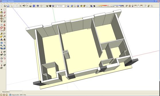
Figure 21: IFC Start-Up Model opened in SketchUp
Table 13: Start-Up Model - SketchUp
|
Element geometry |
|
|
|
Element relative position |
|
|
|
Element colour coding |
|
|
|
Entity and element count |
|
|
|
Schedule of values (spot-check) |
|
|
|
Entity attributes |
|
Some missing |
|
Entity property sets (entity Psets) |
|
Not visible |
|
Model tree-structure |
|
Examination not performed |
The examination disclosed that some of the entity attributes were not listed in the IFC Plug-In palette, i.e. the descriptions. Entity Psets were also not found.
The above concluded the examination of the IFC Start-Up Model while being viewed by the software applications used by the project stakeholders.
5.3 Assembling and Testing Interdisciplinary Model
This sub-section provides the remaining answers to the Research Question 1 and identifies further specific interoperability issues. Additionally, it offers additional in-depth answers to the Research Question 2 regarding selection of criteria used in modeling conformance checks.
Having access to Start-Up Model on model server, each Consultant could use the relevant portions of the model to develop specific design utilising its own proprietary software applications as listed in Section 2.2 Literature Review. At any stage Consultants could save their work to IFC and download their respective models back to model server. The individual models are shown in Figures below and were evaluated primarily against the element geometry, the relative position, entity and element count and schedule of values. The findings summarised previously in the tables have been updated where necessary.
(Architects-Detail Design: Architectural Design, Model Development)
Architects-Detailed Design developed the Design Development model as shown in the native Digital Project file in Figure 22.
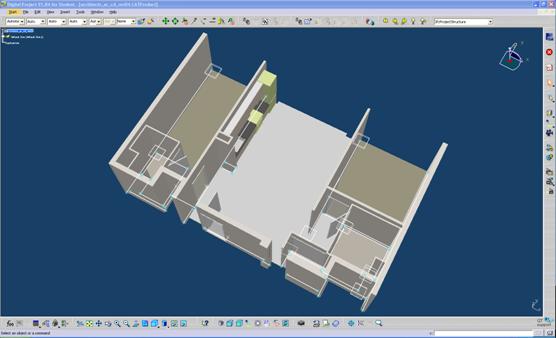
Figure 22: Architects-Detail Design model, Design Development, Digital Project - CATProduct file
The Digital Project native CATProduct file exported to IFC and opened back in Digital Project exhibited a number of issues, as shown in Figure 23 that are mostly round-tripping related.
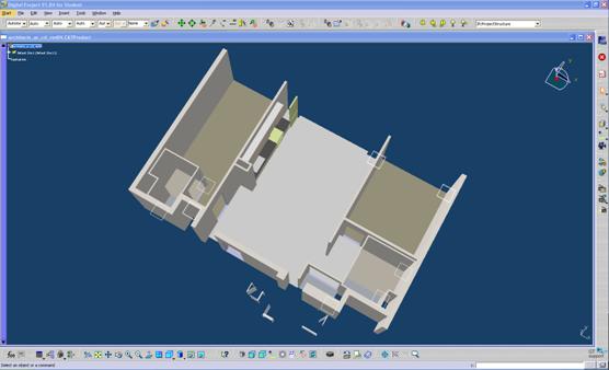
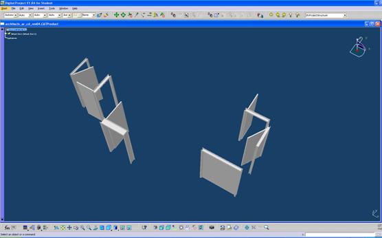
Figure 23: Architects-Detail Design model, Design Development, Digital Project - IFC file
All the doors representing IfcDoor entity were found significantly displaced, and being a number of storeys below the remaining parts of the model. Parts of the object refrigeratior-01 was found missing, leaving the void space behind the enclosure cabinetry.
In avoidance of inconsistencies found above, the model was exported again, this time in parts, with separate files generated for objects representing entities such as (1) IfcSlab, (2) IfcWallStandardCase, (3) IfcElementProxy, and (4) IfcFurnishingElement, as shown in the Figure 24 screenshots.
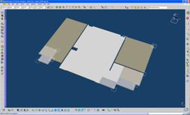
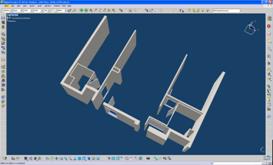
(1) (2)
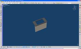
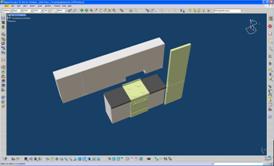
(3) (4)
Figure 24: Architects-Detail Design model, Digital Project - separate IFC files for each entity with its elements
With the approach above, the model was significantly improved, and the only remaining inconsistency was missing components of an object. This is reflected in Table 14 which revises the summary given previously in Table 8.
Table 14: Architects (AR_DD) model - Digital Project (revised Table 8)
|
Element geometry |
|
Some geometry lost |
|
Element relative position |
|
Issues with complete model export |
|
Element colour coding |
|
|
|
Entity and element count |
|
|
|
Schedule of values (spot-check) |
|
|
|
Entity attributes |
|
Description not visible |
|
Entity property sets (entity Psets) |
|
Some Psets not visible |
|
Model tree-structure |
|
|
The previous table for Digital Project was therefore updated with the new findings related to the issues with element geometry and element relative position found in Architects-Detail Design model.
Background and Finding 13
(Envelope Designers: Façade and Balcony Design)
Envelope Designers model, as shown in Figure 25, have not exhibited any inaccuracies in terms of the element geometry, relative position of the elements, entity and element count, and schedule of values.
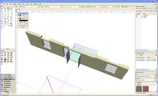
Figure 25: Envelope Designers model, Envelope Design, Vectorworks - IFC file
Background and Finding 14
(Civil & Structural Engineers: Structural Design)
Following the similar check as for previous specialist models, Civil and Structural Engineers completed modeling of their scope in MicroStation, exported the native file to IFC and opened back the IFC file in MicroStation. The screenshots of the IFC file is shown in Figure 26.
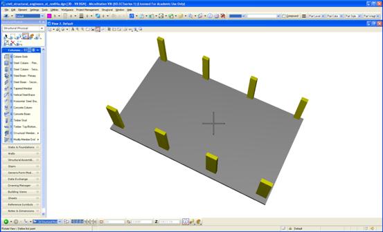
Figure 26: Civil and Structural Engineers model, Structural Engineering, MicroStation - IFC file
No immediate issues were found during the visual examination of Civil and Structural Engineers model.
Background and Finding 15
(Building Service Engineers: Sanitary and Ventilation Design)
Building Service Engineers IFC model, as shown in Figure 27 appeared to be accurate in terms of graphical representation, particularly while checking for the element geometry, their relative position, entity and element count, and schedule of values.
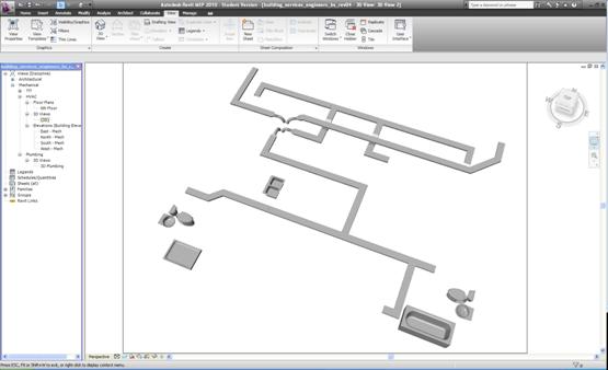
Figure 27: Building Services Engineers model, Mechanical & Plumbing, Revit - IFC file
The steps above concluded production of the individual interdisciplinary models.
Background and Finding 16
(Interdisciplinary Model and Model Server)
Upon completion of the individual specialist designs, the corresponding IFC models were deposited in model server, being made at the same time available for examination by the members of the project team.
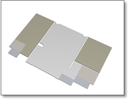 ....
....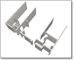


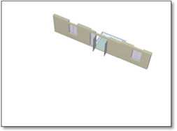
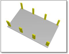
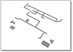
Figure 28: Specialist IFC models from interdisciplinary team before the assembly
The model undergone additional quality assurance and conformance checks, utilising Solibri Model Checker, the software for analysing BIM models to visualise it and look for potential problems. The decision to utilise Solibri Model Checker, instead of highly popular Autodesk NavisWorks[11], was driven by Solibris specific IFC-built engine, its file compression capability, its attention to BIM information, rule-based functionality, and quality assurance functionality, rather than primary attention to geometry-based information as found in NavisWorks (Solibri, 2010).
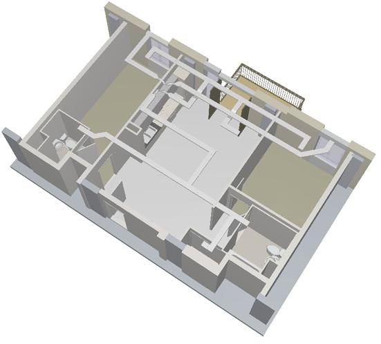
Figure 29: Fully assembled interdisciplinary IFC 3D model
Based on the visual examination, the fully assembled interdisciplinary model, as shown in Figure 29, has displayed none of the geometry-related issues identified in previous compliance checks. All the geometry issues which emerged during the testing, whether related to element geometry or element relative position, have been resolved.
As initially observed by Khemlani (2004), testing the models proves that interoperability problems will most certainly be caused by lack of attention to the way IFC files are created for export. This has been found very true in the testing undertaken in this Research Report. Examples of files affected by inappropriately utilised software settings during the transition process to IFC can be found in Appendix 1 - Supporting Documents under Section 2.4 Proprietary Software Settings vs. Accurate IFC Model.
One of the key issues that has emerged during the testing was the lack of agreement on a collection of a common vocabulary, similar to the findings in Yang (2003). A number of non-standard Psets had been found during the testing, as seen in Figure 10 and Appendix 1 - Supporting Documents under Section 2.3 IFC File Analyzer: Spreadsheet of Start-Up Model IFC File. Such Psets significantly contribute to lack of interoperability. Non-standards Pset were further analysed and solutions sought as in Appendix 1 - Supporting Documents under Section 2.6 Non_Standard Psets.
The key contributor to resolving geometry-related interoperability issues, and at the same time assuring successful IFC export, was the attention to the workflow as well as splitting various objects into components. In the end, the geometry of the fully assembled interdisciplinary IFC model has been found compliant but required very careful monitoring and adjustments on a case-by-case basis. The geometry issues were particularly applicable to ArchiCAD, Digital Project, and Constructor. Resolution of these issues was found very necessary, as corrupted geometry would affect the remaining areas of the model, like entities, element count, schedule of values, entity attributes, Entity Psets, and the overall model tree structure. The summary of the examination results have been shown in Table 15.
Table 15: Examination results - summary
|
|
Solibri Model Viewer |
DDS-CAD Viewer |
Nemetschek IFC Viewer |
IFC Engine Viewer |
ArchiCAD |
Digital Project |
Vectorworks |
MicroStation |
Revit |
Constructor |
SketchUp |
|
Element geometry |
|
|
|
|
|
|
|
|
|
|
|
|
Element relative position |
|
|
|
|
|
|
|
|
|
|
|
|
Element colour coding |
|
|
|
|
|
|
|
|
|
|
|
|
Entity and element count |
|
|
|
|
|
|
|
|
|
|
|
|
Schedule of values |
|
|
|
|
|
|
|
|
|
|
|
|
Entity attributes |
|
|
|
|
|
|
|
|
|
|
|
|
Entity Psets |
|
|
|
|
|
|
|
|
|
|
|
|
Model tree-structure |
|
|
|
|
|
|
|
|
|
|
|
The references below are made to the model integrity checks criteria listed in the summary Table 15:
ELEMENT COLOUR CODING has shown inconsistencies, but only for the models processed with viewers - specifically DDS-CAD Viewer and IFC Engine Viewer in contrast to models processed with the original authoring software applications.
In five out of eleven modeling scenarios, ENTITY AND ELEMENT COUNT has been compliant across all the applications, apart from MicroStation where one of the entity listing was incomplete missing a single entity, and Revit which was not tested in this area.
SCHEDULE OF VALUES has appeared accurate for most of the applications, but there were software packages, particularly Vectorworks, Revit and Constructor, which have not provided complete bill of quantities or have exhibited discrepancies in the values.
Less than the half the software applications utilised in the testing have not retained Start-Up Model ENTITY ATTRIBUTES in their IFC models. Some of the attributes, and in certain cases all of them, have been missing; others have had incorrect names inherited from the adjacent elements.
ENTITY PSETS have been found accurate for all the IFC viewers, but have caused significant issue for all the authoring applications with the exception of ArchiCAD. The issues comprises of missing some or all the Psets.
MODEL TREE-STRUCTURE in all the examined models had been consistent with the previous findings.
The testing disclosed that in terms of software the most reliable applications in terms of handling IFC models are IFC viewers in contrast with the model authoring applications. The authoring applications issues however, are normally non-geometry related. ArchiCAD has been identified as the front runner in terms of IFC model reliability, but it needs to be realised that unlike the remaining applications, it has been used to generate Start-Up Model and has been fronting the workflow. Vectorworks and SketchUp have followed, bearing in mind the applications contrasting capabilities.
Background and Finding 17
(IfcXML Conversions)
Further conformance checks performed for ifcXML files involved compliance methodologies dependant on which approach was used to generate the ifcXML file. Such approaches were data mapping approach or data direct approach discussed in sub-section ifcXML of Section 2.2 Literature Review. IfcXML files generated with data mapping approach, involving translation of IFC data to XML, depend on conversion of the native model to IFC, and therefore are exposed to inheriting of any data loss through such conversion. IFC file quality assurance checks constitute therefore an early warning to what should be expected in the converted ifcXML model. IfcXML files that are by-product of extraction of XML data directly from CAD file using data direct extraction approach still depend of IFC, as its schema is mapped to XML, but are independent from any conversions of the model to IFC file and the quality of such conversions. Data direct extraction approach is illustrated in Figure 30 with the 3D object and the corresponding ifcXML file extracts listing the model elements, their entities, and the associated attributes and properties.
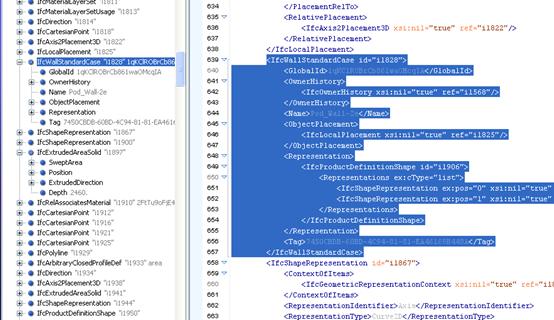
|
|
Wall element represented by IfcWallStandardCase entity |
|
|
|
|
|
Door element represented by IfcDoor entity |
|
|
|


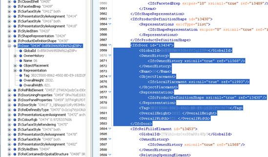
Figure 30: ifcXML file generated from 3D model with data direct extraction approach
5.4 Other Interoperability Issues
This section covers Research Question 3 through Research Question 14 listed in Section 3.3 Research Questions, and referred within the text of each sub-section below.
Interoperability: Standards vs. Software
This section answers the Research Question 3 seeking the source of interoperability issues, whether they come from software itself or the standards. The section further describes how software vendors cope with advances of development of the standards.
It has been recognised through the testing and the literature review that interoperability issues are triggered by a combination such of factors as (1) the interoperability standard-related and (2) proprietary software-related. Attention has been paid in the Research Report to the way how IFC files are generated by understanding and carefully applying the proprietary software export settings. Such settings and the related options vary from software to software. Interoperability standards adopted by the software applications require agreement on a collection of a common vocabulary, entities, properties, and Psets from the start. The testing has disclosed that each individual software application returns different set of interoperability issues. Each and every application tested was not capable of generating a file identical to the one created with the original model authoring application. More work is required by both, interoperability standards bodies and software vendors, to resolve this issues. The standards - IFC specifically - need further development in terms of stabilising entity definitions and extending the ability of the model to cover more areas in various AEC domains, like planning, design, construction, cost, programme/schedule, and facility operation. This needs to be supported by obtaining ISO certification for the remaining parts of the IFC Object Model (Khemlani, 2004). Software vendors need to catch-up with the advances of standarisation. Many of them tend to heavily advertise abilities of their software in adopting IFC, but only a handful of them have received the formal IFC certification from IAI. Among the software used in this Research Report, the Step 2 certification that involves the IFC interfaces being tested against selected project files arriving from beta customers, are only achieved by previous versions of the software, such as ArchiCAD 11, Bentley Architecture 8.9.3, Revit Building 2008 SP1, and Solibri Model Checker. None of this software latest releases are Step 2 certified. The latest batch of Step 2 certification was issued to the above vendors in March 2007 (buildingSMART, 2010b). This gives an indication that the current software applications may not become IFC Step 2 certified until at least three and the half years from the time of release the latest versions. It is therefore expected, that software vendors will continuously try to catch up with the advances of standards and the certification. The market will continue to be filled with a mixture of the outdated IFC-certified software applications and the current releases of the IFC non-certified applications, deepening the challenges in addressing interoperability issues.
Interoperability and data extraction
The answer to the Research Question 4 looks into a link between interoperability and effective extraction of data or information from systems.
The answer could be provided by realising that the interoperability standards such as ifcXML, map between the IFC object model geometrical and the non-geometrical, document-based representations, such as schedules, tracking documents, bill of quantities, and product datasheets. Such standards connect also with the model message based representations, i.e. RFI process (Request For Information), instructions, and orders, and the range of other eCommerce communications. Apart from facilitating transmissions and merging models, ifcXML, as XML representation of IFC model data, plays a key role in effective extraction of model data and information in collaborative processes (International Alliance for Interoperability, 2007).
Value of Interoperability
The Research Question 5 refers to value of interoperability, its importance, its affects on interdisciplinary collaboration, and finally its quantification.
The reply to the subject question invites the statement that interoperability affects entire AEC industry, involving the build teams who utilise wide variety of specialist software applications and share the data among the interdisciplinary teams. Interoperability issues only interfere and hold back that exchange, leading to inefficiencies, abortive work, and errors. The industry sees the software incompatibility issues as a key factor hampering the build teams ability to share information. Deficiencies in interoperability affect workflows and have direct impact on project programme/schedule and budgets. The excess cost and programme/schedule implications are mostly caused by manual re-entry of data from application to application, therefore duplicating the tasks by project members. The costs are also attracted by using duplicate software and the time lost due to document version checking and ineffective processing the information. The $15.8 billion price tag quoted in Chapter 1 comprises of two-thirds of these costs being borne by owners and operators mostly during facility operation and maintenance (Young et al., 2007). This quantifiable interoperability cost data and the estimation methodology integrated data has been collected from a variety of sources via interviews and surveys (Gallaher et al., 2004). Similarly, based on surveys and using estimates of past, current and future usage of BIM, the 2007 interoperability issue of McGraw Hill Construction SmartMarket Report states that on average, 3.1% of project costs incurred by clients, designers and contractors are related to software non-interoperability. The above quantification was supported with two case studies, for General Motors and United States Coast Guard, and provided more quantifications (Young et al., 2007). In addition, interoperability of BIM software application greatly impact on projects quality assurance, and most importantly affects customer satisfaction.
Standards - Good Standards
The Research Question 6 raises the issue of what it actually means to have a good standard.
In AEC and BIM context standards must be open and should facilitate capturing, organising, distributing., exchanging, and using the information, as well as to promote innovation in processes and infrastructure for the efficient and quality delivery of facilities (National Institute of Building Sciences, 2010). The objective of standards is also to provide means of describing product data throughout the lifecycle of a facility, which allows project stakeholders to work across different platform and software applications with data continuity (Serror, 2006). Standards should contribute to effective transfer of data between different phases of the project, support collaboration and communication, automation, and integration of the design, construction, operation of facilities, and in general should improve efficiency in service delivery by interdisciplinary teams (Gallaher et al., 2004). Good standards should be also international, thus dealing with different cultural backgrounds and languages. The close attention should be paid to any dynamic extension mechanisms which would transmit standards into different dialects that are only agreed between a handful of collaborating parties, resulting in incompatible solutions (Weise et al., no year). Most of the standards share the commonly agreed set of labels, entity definitions and relationships intended for exchange of diverse information and for defining project models. These tasks need to ensure the consistent interpretation of application semantics across all the AEC disciplines and to achieve semantic interoperability (Yang and Zhang, 2006).
Criteria for evaluating good standards could be established with various approaches; They may follow criteria used for evaluating good programming languages, e.g. these adopted for evaluation of software prototyping experiment found in Hudak and Jones (1994). If such approach is adopted, than a standard should be characterised by its (1) extensibility, meaning ease of being extended to meet any additional requirements, (2) understandability, in the context of speed of absorbing and altering the application, (3) appropriates, referring to how expressive it is in relation to task it performs, (4) accuracy, meaning correct functioning, and finally (5) compactness, being capability of each line of code (Hudak and Jones, 1994).
A good standard is characterised by its expressive nature, it expansibility, and by having a facility for a standard way of addressing non-standard extensions. It is further characterised by its wide implementation and popularity, proving its wide acceptance by individuals and organisations, and through standards bodies giving opportunity for anyone to participate in the process of its development and improvement. It is finally characterised by its ability to be used anywhere by being platform and language-independent.
Exploring IFC (and ifcXML) as a Standard
This section looks specifically at IFC, as well as ifcXML, and answers the Research Question 7 by investigating the origination of the standards, whether these standards are sufficiently mature, and whether they address the intended needs.
AEC standards organisations like NIBS fall in equation of W3C Recommendations. NIBS, through their National Building Information Model Standard Project, have been taking part of specification and standardisation activities, involving standardised machine-readable information models (The National Institute of Building Sciences, 2005). These models have a wide adoption of XML by mapping IFC schema into ifcXML and are increasingly exchanged over the Internet.
IFC model facilitates development of different types of products and categories of functionality to reduce a chance for variations of interpretations by different software vendors. This is instrumented by introduction of specialised, industry-standard views of IFC model, such as Data Model for Data Exchange and Standard Interface Definitions. The IFC Object Model as seen in Figure 2 provides for a set of well defined ways of breaking down information into logical groups or classes along with their related information about the model objects. It is however recognised that the model is not complete due to variation of information users would want to exchange. This limited inclusion of classes is intentional as it controls a size of the model. In order to allow for the model extensibility, it is possible for many classes to define new Types of an element, creating at the same time a standardised ways of describing information (International Alliance for Interoperability, 1999). Expansibility of the specification is addressed by employing the individual proprietary softwares IFC property extension mechanisms to define custom IFC properties and Psets. These extension mechanisms provide more flexibility to property definitions meeting the user requirements and making them application-specific (Yang and Zhang, 2006).
IfcXML on the other side, being an emerging industry standard, becomes adopted as a knowledge representation format, has the ability to model data from various AEC industry project management applications related to geometry, product data, process and activity information, and provides XML-based schemas accommodating querying and transferring information over the Internet (Cheng et al., 2003).
In terms of answering all the current interoperability issues by IFC or ifcXML, these standards do not sufficiently ensure consistent interpretation and understanding of application semantics, i.e. meaning of the respective terminologies utilised among all participating teams and applications (Yang and Zhang, 2006). As previously indicated, one of the benefits of IFC and its schema is to keep the standard as compact as possible, and the attempt of satisfying the specifications semantic interoperability may not be practical.
Besides the interoperability standardisation approach which this Research Report concentrates on, another key technology may be considered to address the issue of semantic interoperability, and such technology is ontology engineering. In this technology, the meanings of any terminologies or properties are specified in the formal language such as OWL (Web Ontology Language) or RDF (Resource Description Framework) and their ontological definitions (Yang and Zhang, 2006).
Interoperability and Trust
The Research Question 8 looks into the issue of interoperability in terms how reliable it is and whether the information processed through the interoperable means gives full comfort in terms of its accuracy.
Complex projects with vast amount of data exchanged among the stakeholders question the accuracy of the transmitted information, whether no data loss took place and whether the information was error-free. This issue was part of Authors hands-on experience while participating in Harvard School of Design case study on information technology for collaboration (Pollalis, 2005). Testing of models in this Research Report proved that information is one way or another affected by the exchange between the applications during the collaborative process of project delivery. Despite the geometry being not the mayor issue, as it could be brought to compliance by methods identified in the previous sections of this Research Report, any non-geometric and semantic content constitutes a threat due to its volume and due to the difficulty to spot it by the naked eye. The issue could be only addressed by careful adoption of interoperability tools and continuous monitoring on a case-by-case basis. There is no evidence however, that such tools and processes would give a full comfort of achieving interoperable BIM.
There are a few tools available today, such as Solibri Model checker, that are designed for the purpose of addressing models integrity and its compliance by utilising methods of quality assurance and control (Kulusjärvi et al., 2010). By adopting standardised processes of quality control, which such tools support, the project team develops trust in the information contained in the model (Tiwari et al., 2009).
The issue of inaccuracies and information trust cannot be evaluated without looking at alternatives, such as traditional approaches. An example would be a cost estimate excercise for building projects, which traditionally starts with a time-consuming process of collating components from printed or CAD drawings. From the obtained quantities, estimators would normally utilise methods, such spreadsheets or costing software applications, to produce project cost estimate. As observed by Sabol (2008), processes like this have a natural inclination to human error and tend to result with inaccuracies. It may take substantial resources and time to sufficiently address these without automation, still with no guaranteed results. Any interoperability issues and the related potential errors affecting trust in BIM projects need to be evaluated against traditional approaches. Once evaluated, it could be confirmed that BIM, with its known interoperability issues, offers the capability to develop project information with more accuracy (Sabol, 2008). Similar findings emerged in two other separate initiatives, being Staub-French (2003) and Jadid and Idrees (2007), further illustrating cost estimation approaches utilising IFC.
Interdisciplinary Collaboration
The Research Question 9 addresses interdisciplinary collaboration in BIM and its impact on the systems interoperability.
With the newly developing concept of BIM, collaborative approach of the interdisciplinary stakeholders is also new. Traditional interactions among the project members have been always based on personal contacts, with the use of phone, written correspondence, or sporadically with video-conferencing technologies. Paper or electronic copies of the documents were exchanged by hand or e-mail. The issue of interoperability was virtually non-existent.
With the development of BIM and the parallel drive for efficiency by exploring new ways of project delivery, the two needed to be considered in conjunction with each another. This BIM-efficiency assembly introduced a new interface, the partnership between BIM (with its teething symptoms) and collaboration. Architecture, engineering, construction and facility management fields have started to apply methods and lessons learnt originated in other industries, like automobile, aeronautical and shipbuilding. The project delivery methods like concurrent engineering and IPD, that collaboratively puts people talents together, started to dominate the market. This, in contrast with Project Management, General Contracting, Design-Build and Construction Management approaches mentioned in Section 2.2 Literature Review, provides for increased integration of people and the systems. Such integration transfers any project team related issues, along with the utilized methods and tools involving computer software, directly into BIM process and the delivery. With the workflows no longer providing for simple sequential stakeholder-to-stakeholder delivery, the systems and the related interoperability need to account for complex flow and multiple exchanges of data, which in turn invites the previously noted issues of round-tripping.
The recommendation to improve interoperability in light of modern approaches of project delivery, specifically related to interdisciplinary collaboration, is to recognise that standards like IFC or ifcXML do have limitations. This has been noted in Section 2.2 Literature Review under Data Models/Specifications/Standards. Further on, the recommendation is for the project stakeholders to continue learning about specifics of such limitations in avoidance of over-expectations, and in order to adjust applicable parts of workflows early in the process as per interoperability specification capabilities, e.g. by taking a view on utilisation of round-tripping or whether it should be considered at all.
Interoperability Obstacles and Ways for Improvement
This sub-section addresses the Research Question 10 and its key issue of the source of interoperability problems, the obstacles, and how to remove them.
Key factor inviting interoperability issues is the continually advancing and complex nature of AEC projects today, the volume of specialism disciplines involved, and the software solutions employed. Based on the statistics quoted earlier in the Research Report, there are still early days for implementation of BIM and the technologies it brings. This is deepened by companies diversified management approaches and the wide range of processes they use. Blending the above with benefits of interdisciplinary collaborative approach, companies are left with evolving technology and the need of improving it. This Research Report exhibits that there is no single factor causing interoperability issues among BIM software applications. Instead, there are numerous factors in place, as exhibited through the literature review and the model prototyping and testing. These factors, although examined only partially, can be used as a practical advice on how to remove the obstacles in attempt to increasing the chance of achieving interoperable BIM in collaborative AEC projects.
Successful project should begin with establishing a well-thought process and coordination workflow. Many software translators are not designed for multiple exchanges, and work only in one specified direction. The software may convert the model well and export it, but then could return with corrupted files by merging the model back to its repository. Implementation of appropriate workflow-based translators needs to match the workflow requirements, and the effort is required to accurately define IFC Views for the project-specific workflows (Eastman et al., 2008). This should follow with examination of the process flow diagrams and verification of these with the software functionality through testing.
A collection of the common vocabulary should be agreed early on. By complying with the vocabulary any misinterpretations of shared information would be minimised, if not eliminated. The way to define and maintain a common vocabulary database is to define new entity properties, or modify the existing ones, bearing in mind the naming constraints imposed by the common vocabulary. Non-standard Psets need to be examined and the naming agreed, or agreements should be made on reaching compromised interoperability level.
Attention should be paid to the software settings while translating the model from its native file. This is one of the key factors in determining how successful the interoperability would be. It is often the safest to use softwares default settings, but this needs to be tested on a case-by-case basis.
Separating elements of the model has been found a very effective way of resolving issues of the displaced geometry of individual objects, as experienced in Digital Project model illustrated under Background and Finding 12. Splitting the models into components needs to be considered in light of parametric nature of objects, which frequently would translate more effectively in isolation. Psets need to be examined in order to establish independencies between objects and effectively arrive with translation protocols; More work in this Research Report had been put towards resolution of this issue in attempt to successfully resolve the problem in other applications, such as Constructor. These additional tests are included in Appendix 1 - Supporting Documents under Section 2.5 Separating Elements or Objects.
Power of XML should be recognised, and all possible steps should be taken towards utilisation of ifcXML. While generating ifcXML files, it appears that a data direct extraction approach, involving generating XML data directly from CAD model, is more reliable than the two-step data mapping approach where ifcXML is being generated from IFC file.
Continues effort should be maintained by software vendors to certify their latest versions of applications, and by buildingSMART to obtain ISO certification for the remaining parts of the IFC Object Model and to improve IFC certification process.
Although IFC is the de facto format for BIM models today, other standards or specifications should be considered to use in combination. Although interfaces between the employed standards solution may cause challenges, the use of multiple standards would only increase a chance of interoperable model or its components.
Continues education about standards would help managing expectations. It needs to be realised that it is unrealistic to expect complete level of interoperability among the authoring software applications. Good step towards improving interoperability would be to differentiate the model information best suited for transmitting in a non-proprietary format (such as IFC or ifcXML), from the information intended for the exchange while employing proprietary software programs such as original authoring applications. This should follow with examination of vulnerable areas of the files on how they behave upon adoption of each of the above approaches.
Once parametric model interoperability is under control, and the uncertainties are effectively managed, the 3D model may be extended to additional dimensions, like 4D, 5D, and beyond, to continue mastering of the earlier adopted prototyping and testing methodologies.
Software vendors and the users should be encouraged to take a part of the standardisation process by performing interoperability testing, actively participating in standards organisations like buildingSMART, and sharing the results with others.
5.5 Conclusions
Chapter 5 concentrates on providing the answers to the questions listed in Section 3.3 Research Questions. These have been comprehensively addressed by employing a series of activities leading to building and testing digital models that are utilised in interdisciplinary workflows. The activities have been supported by the literature review. This has led to the findings that answered the research questions, and resulted with the related recommendations.
In reply to Research Question 1, the methods used to disclose the interoperability issues should involve in the first instance adoption of workflows for information production and exchange, with collaboration in mind. This should be followed by examination of the BIM process, modeling involved, computer applications used, and the applicable interoperability standards utilised, with particular attention to IFC, and ifcXML in the background. The methods for disclosing software application interoperability issues should further involve assembling digital prototypes of interdisciplinary models and testing these. Some testing methodology may require adoption of round-tripping, often unavoidable in AEC workflows. Separate methods may be established for the examination of ifcXML, with data mapping and a data direct extraction approaches in mind. Effective testing requires a set of criteria intended for the conformance checks. The tests should utilise more than one, ideally several, software applications, including IFC File Analyzer, a conformance assessment tool, which is used to evaluate coverage of IFC product data model files. Solibri Model Checker should be also employed to analyse BIM models by visual examination methods.
In terms of listing the particular interoperability issues, this can only be established on a case-by-case basis through the adoption of project-specific workflows, software applications utilised, the given modeling scope, and would depend on the project size and complexity. To address this question in general terms, it is only possible to arrive with a prognosis, as summarised below, and based on the prototyping and testing utilised in this Research Report.
It is expected that model conformance testing would first disclose issues with 2D information. Testing in this Research Report has made it clear that IFC is not ready, and otherwise inappropriate, for handling 2D files. The attention should be paid to the proprietary software IFC settings, which may be misleading and give incorrect impression of the interoperable 2D. As the research should be concentrating on parametric modeling, the remaining interoperability issues would be 3D[12] related. Close attention should be paid to non-standard Psets, some of which may not be found interoperable across the software applications utilised in BIM. Testing of element geometry and element relative position would most likely disclose interoperability issues initially, but these in the end should be resolved. Methods exist to address the geometry-related parametric model interoperability issues, with some of them utilised in this Research Report. Similarly to the issues experienced with proprietary software settings for 2D models, parametric file translation settings often result in corrupted models. Further on, entity and element count and schedule of values may be found incorrect as a result of the translation process. Problems may occur with missing model entity attributes or attributes carrying incorrect names. Significant interoperability issues should be expected if Psets are found incomplete or missing.
Research Question 2 criteria established to examine interoperability in BIM should include examination of IFC model elements, their geometry, the relative position, and the colour coding. They should also include the entity and element count, a spot check on the schedule of values, examination of entity attributes and Psets, and a review of the model tree structure. Such criteria form a base of effective testing to establish whether the translated model is compliant and integral, with no data loss when compared with the model generated with the original authoring application.
Interoperability issues as referred in Research Question 3, have been resulted from both, software as well as the standards. During the process of testing, the files exported to IFC have returned a range of interoperability issues. The files were never identical when compared with the ones initiated in the original model authoring applications. Software vendors are continuously striving towards aligning their applications with the latest requirements of the standards. This is an ongoing process, and it currently takes as long as three to four years from the software release to its certification. During this time, newer versions of software applications are released, and nothing indicates that it will ever come to the point that the latest version is Step 2 IFC certified.
The link between interoperability and extraction of data from the model, referred to in Research Question 4, has been seen in IFC, as well as in ifcXML. IfcXML maps between the IFC object model geometrical and the non-geometrical, document-based representations and also connects with the model message based representations, which provides at the same time a facility of effective data extraction.
The Research Question 5 refers to the value and importance of interoperability in the AEC industry and has been raised in recognition to the affects of interoperability on collaboration and sharing data among interdisciplinary teams. Unresolved interoperability issues hold back exchange of information affecting the workflows and lead to work inefficiencies, abortive work, errors, and quality assurance issues. Interoperability visibly interrupts interdisciplinary collaboration by restricting free and accurate exchange of project information. This impacts on the project programmes/schedules and budgets. Interoperability issues and its impact have been already quantified, and the industry losses are measured in billions of dollars.
A good standard, referenced in Research Question 6, is characterised by its open nature to facilitate organising, distributing, exchanging, and using data and information towards efficient and quality delivery of projects. Open means being implemented and used by all, in this case AEC software vendors. A good standard is characterised by being platform and language-independent. It further allows description of product data in such a way, so project stakeholders would be free to work across different platform and software applications, still maintaining data continuity. Good standards share the commonly agreed set of labels, entity definitions, and relationships, ensuring the consistent interpretation of semantics across the AEC domains. Any dynamic extensions mechanisms transmitting standards into different dialects need to be carefully monitored not to allow for incompatible solutions. A good standard needs to be expressive in its nature, expandable, and must provide a facility of standard ways of addressing non-standard extensions. Other characteristics of a good standard include qualities, such as extensibility, understandability, appropriateness, accuracy, and wide popularity and adoption. Quality standards evolve over time, with memberships of the standards organisations being open to any company wishing to participate.
The issue of IFC and its place among goods standards has been raised in Research Question 7. The history of IFC specification reaches back to 1995 when the standard was created using the EXPRESS data definition language. IFC was developed by BuildingSMART, an alliance of international organisations dedicated to improving processes used within the AEC industry with the particular attention to sharing the information. IFC became the de facto standard in the AEC industry. The IFC Object Model is incomplete, but this has been found often intentional. Due to variations of data in place the users want to exchange variety of information using BIM, and completing Object Model would restrict flexibility of information exchange. Views are utilized in the model to facilitate development of different types of products, services, and categories of functionality to accommodate various interpretations of the model by software applications. Model extensibility is instrumented by model classes that define new types of elements, which in turn provide for a standardised way of describing information. IFCs expansibility is addressed by employing its property extension mechanisms to define custom IFC properties and Psets. This gives more flexibility to property definitions. IFC, being the lowest common denominator, reduces functions found in proprietary software, which sometimes back-fires with interoperability issues such as model data loss and file corruption during round-tripping. In terms of semantic interoperability, IFC, as well as ifcXML, do not sufficiently ensure consistent interpretation of meanings of respective terminologies utilised among the project teams and software applications. Despite the above, IFC is sufficiently mature to be utilised as AEC standard, with most of its imperfections being well reasoned and already put forward for improvement.
Reliability of interoperability brought up in Research Question 8 starts with the models geometry, being the immediately visible element of the model. With the methods employed in this research, it was found possible to rely on IFC or ifcXML when it came to the exchange of purely geometry-related data. The process however, needed to be supported by traditional, manual visual inspections. The remaining non-geometric data, i.e. related to the model entities, properties, ands Psets, may be a cause of concern. With no common and proved methods in place to provide a rigorous determination or measures of the IFC file content, BIM users rely on their own approaches and tools for file conformance checks. This leaves the users with an open question what issues to expect in the interdisciplinary model until such approaches and tools are developed and applied. Data exchange among the applications cannot be trusted without employing digital model prototyping and testing and evaluating these against a traditional approach of manual checks, similarly to the methods utilised in the Research Report. The data in an IFC file and the source file created in the original authoring application will never match. It is important to realise this, and by the way of familiarisation with the specifics of un-interoperability, target the functional elements of data translation.
Research Question 9 looks into interoperability from the perspective of interrelations among the team stakeholders, who experience the visible change in methods of working on projects utilising BIM and the related technologies. In past, a separate digital information model would be produced for each stage of the project. The models were generated with different software applications of various file formats, with no need of interoperability among them, as they were discarded upon completion of each stage, and the new ones were produced from scratch for later phases. Utilising an IPD-like way of delivering projects today, simple sequential stakeholder-to-stakeholder or stage-to-stage delivery of information is no longer accepted. With overlapping stages of delivery, the project data is continuously exchanged between team players, and the software applications employed in such situations need to effectively interact between each other. To minimise current interoperability issues, it is necessary in the first instance to examine the projects workflow and apply any adjustments to the process, with software functionality and capability of its translators in mind.
There are numerous of areas inviting interoperability issues, as raised in Research Question 10. The key area is the growing amount of software solutions utilised by interdisciplinary teams in increasingly complex AEC projects. This is followed by the early days of BIM as we see it today and the associated evolving processes, along with a lack of familiarity and experience in adopting them. The interoperability issues should be in the first instance mitigated by establishing appropriate coordination workflows. This should follow with agreeing on the collection of a common vocabulary. Utilising IFC for 2D interoperability has been found inappropriate and standards like DXF, or formats such as PDF, should be used instead, as these provide the most effective way of exchanging 2D information in AEC. The IFC file translation settings offered by proprietary software applications need to be carefully evaluated and tested, and then used with caution. Without this, just pure reliance on software settings, even the default ones, brings unexpected results. Another way to affectively overcome the issue of a corrupted model returned through IFC translation is to examine their Psets and separate their elements as appropriate. Non-standard property sets contribute to interoperability issues, and agreement needs to be reached on collection of a common vocabulary. Standards like IFC need further development to stabilise entity definitions and extended ability of the model to cover more domain areas of AEC. Standards need to progress towards ISO certifications for the remaining parts of the IFC Object Models. Additionally, IFC deficiencies found in semantic interoperability could be addressed by employing ontology engineering and the languages or standards such OWL and RDF. IFC-to-ifcXML translation issues can be minimised by choosing a data direct extraction approach, as it is independent from any conversions of the native model file to IFC, and therefore not being impacted by the quality of such conversions. All efforts should be made to improve IFC certification with active participation of the AEC professionals. It needs to be realised that IFC is not the sole standard utilised in the AEC industry. IFC may prevail, but other specifications, such as ifcXML or CIS/2, should be considered for effective data exchange. IfcXML specifically, with its simplicity and wide adoption of XML, gives a wide range of interoperability opportunities. The AEC professionals and software vendors should continuously educate themselves about the standards, utilise the technologies in their projects, instrument interoperability testing, and exchange the experiences with others.
6.1 Introduction
Each chapter of this Research Report may be seen as a piece of stand-alone work with its own introduction, main text body, findings, and conclusions. This chapter does not attempt to revisit each and individual literature review issue or the research question undertaken in the Research Report. Instead, it looks at the work as a whole for better understanding of BIM, its interoperability issues, the related interdisciplinary collaboration, and any methodology utilised in the subject research paper. It also provides validation of the hypotheses with the related commentary. Section 6.2 For the Future adds another dimension to the research problem by identifying other work which could be undertaken to reinforce the findings, improve the interoperability, and utilise the knowledge gained during the process of writing this Research Report.
6.2 For the Future
The research problem invites a range of topics that could be extended to other areas, still relevant to BIMs interoperability, but falling outside of this Research Report due to its size limitation and the time restriction. The knowledge gained during the course, and while writing this Research Report, brings a number of related areas that could be considered for the future.
Additional testing could be instrumented for ifcXML. Upon completion of IFC file testing, taking for consideration the project-specific workflows and agreed project-specific IFC views, the particular IFC schema could be mapped to XML to examine capabilities of the corresponding ifcXML.
A live BIM project could be utilised to implement and integrate standards like IFC and ifcXML, perhaps with the incorporation of additional specialist standards such as CIS/2 for structural steel part of the model.
Other options of sharing BIM information could be investigated, i.e. using emerging technologies such as the iPad applications. Very recently, Autodesk announced their return to AutoCAD for the Mac, bringing 3D free-form design with a graphical user interface, and the option of viewing, editing and sharing files on the iPad, iPhone, and iPod Touch (Autodesk Inc., 2010a).
Once interoperability of 3D files is mastered, BIM could be evaluated for 4D, 5D, and beyond, bringing additional dimensions to the model, such as safety and sustainability to start with.
Examination of interoperability could extend to the areas of semantic interoperability in BIM to further enhance model data exchange and collaboration. This would involve defining a common vocabulary used in the development of shared reference ontology as defined in OWL.
Semantic interoperability could be extended by developing software tools for the building code automated checking and verification of the project clients brief.
New solutions, ready to interoperate, could be developed and sold to the market by the software vendors being now equipped with the ammunition of interoperability quantification and the specific user requirements.
Finally, the knowledge gained in live BIM projects and during prototyping and testing could be shared with other professionals in editorials, presentations, and trade conferences.
6.3 Conclusions
Interoperability issues in light of interdisciplinary collaboration addressed in this Research Report have been seen from the perspective of analysing current adoption of BIM with its workflows, processes, AEC software applications, and the implication of standards. The analyses have been instrumented by examining industry common software standards, identified specific issues, and made recommendations leading to improving interdisciplinary collaboration in BIM. Too many unanswered questions, covering a wide spectrum of BIM, interoperability, standards, interdisciplinary teams, and collaboration, were initially in place to provide a simple set of answers without submerging into the deep process of the methods of investigation, literature review, model prototyping, testing, and drawing the conclusions. Upon identification of the initial questions, the corresponding issues were divided in two groups: (1) the group representing knowledge that already exist, leading to investigating what is already known about the research problem from the literature review, and (2) the group of questions representing issues that needed further investigation through alternative approaches, captured in Section 3.3 Research Questions.
The knowledge that already exists relates to general BIM issues, project stakeholders, project approaches, software applications, interoperability, standards, and data models. IFC has been found the only well developed, non-proprietary, open and public data model for AEC existing today, and therefore utilised throughout the research work in this Research Report. It has emerged that IFC is a standard of a high quality, being expressive, expansible, and providing a facility of a standard way of addressing non-standard extensions. IFC is also sufficiently mature to be utilised in BIM. IFCs link to XML gives added opportunities; therefore, ifcXML should not be underestimated as another global standard and utilised in projects, hand-in-hand with IFC, along with other industry-standard models or electronic data exchange formats like CIS/2.
The issues that needed further investigation were captured in ten carefully formulated research questions. This followed with hypotheses intended for validation upon completion of the research. In preparation to obtain the answers to the research questions, the methodology of investigation has been defined, involving collecting data by producing digital model prototypes and analysing them. At the same time it was realised that any prototyping and testing cannot proceed without a clear set of criteria. Such criteria were developed utilising a preliminary analysis of Start-Up Model and used throughout the testing activities. As the testing progressed, the research questions have been gradually satisfied.
The research has disclosed numerous interoperability related issues, more than indicated in the initial literature review. The issues have been recorded with the knowledge applied to the relevant answers of the research questions. The literature review and prototyping/testing work have provided a basis for an accurate validation of the research hypotheses.
Hypothesis 1 (Success of resolving interoperability issues depends on methods employed to discover such issues) can be validated, as the success of resolving interoperability issues does depend on methods employed to discover such issues. These methods, like prototyping and testing, have been identified and implemented in the research.
Hypothesis 2 (There are known issues with interoperability and such issues could be specifically identified and named) can be also validated, but with comments. There are certainly known issues with interoperability and many of them have been identified in the Research Report. Due to the nature of the methods employed and testing limitations explained earlier in the paper, it is not known to the end whether all of the issues have been identified. In general terms, many issues depend on specifics of the project, such as workflows, software applications used, and standards utilised.
Hypothesis 3 (IFC, as well as ifcXML, are sufficiently mature to be adopted in projects utilising BIM. Teams are prepared to undertake a challenge of interdisciplinary collaboration while submerging in BIM) could be validated, but with caution. IFC as well as ifcXML, are sufficiently mature to be adopted in projects utilising BIM, bearing in mind the indicated earlier initiatives that needed be in place in order to improve the standards. Many teams are prepared to undertake the challenge of utilising the standards, which comes with the increasing popularity of BIM. They will succeed and gain benefits of this approach and the emerging technologies, providing they are sufficiently educated about the standards and are able to recognise the benefits as well as the limitations. Such knowledge about interoperability sometimes amounts to identifying what information can be transmitted in a non-proprietary format like IFC or exchanged by alternative means - or lost altogether - and still provide sufficient basis for interoperability between practices.
With the problem-solving approach of this Research Report there has been always a strong desire of arriving with solutions rather than barriers. The modern story of the Tower of Babel may in the end have a happy ending. Numerous ways have been identified in this Research Report to utilise BIM, together with its interoperability issues and its interdisciplinary collaboration, with the intention to further promote innovation and industrial competitiveness in the AEC area.
Glossary and Definitions
AEC: Architecture, Engineering, Construction
Author: Author of the Research Report, Voytek K. Pniewski
Build team: Team in the AEC industry involved in some or all the tasks related with planning, design, construction, facility management, and demolition of the facility.
Building SMART: An alliance of international organisations dedicated to improving processes used within the AEC industry with particular attention to sharing the information
BIM: Building Information Modeling
Building Model: A digital parametric model of a facility. May be 3D, 4D, 5D, or carry additional dimensions
CAD: Computer Aided Design
CIS/2: CIMSteel Integration Standards
Compliant model: The term compliant pertains to the model and its integrity when compared with the one generated using the original model authoring application. The term compliant model does not constitute compliant design.
Consultants: Architects-Concept Design, Architects-Detail Design, Civil & Structural Engineers, Building Services Engineers, Envelope Designers, Contractors, and Others.
DXF: Data eXchange Format
IFC: Industry Foundation Classes, public, non-proprietary data model and worldwide standard for the AEC industry
IFC Views: IFC subsets, called also Data Exchange Use Cases, used for specifically defined workflow exchanges
ifcXML: A result of translating IFC/EXPRESS source files into XML file format, IFC data file using the XML document structure
Interoperability: Ability to manage and communicate electronic product and project data between collaborating firms and within individual companies, design, construction, maintenance, and business process systems
IFC: Industry Foundation Classes
IPD: Integrated Project Delivery
ISO: International Organization for Standardization
Model integrity: The term used as a characteristic of a model converted to one of the standard interoperable extensions like IFC or ifcXML, with no relevant deviations from its source model created with the original authoring application.
(IFC) model server: Model data sharing platform. For the purpose of this research Solibri Model Checker was utilised as the repository of the IFC information and data.
Modeling: Production and utilisation of digital models in AEC
OWL: Web Ontology Language
Pset: Property Set
RDF: Resource Description Framework
Round-tripping: May apply to importing an IFC-file into the application which exported it or any other IFC-compliant application
Specialism: AEC design discipline, i.e. architecture, structural engineering, building services, etc.
Start-Up Model: Interdisciplinary digital model of a facility generated normally by architects utilised by the remaining design disciplines to commence their individual design
XML: eXtensible Markup Language
This section lists the sources which are cited within the text of this Research Report. Complete list of resources that assisted in gaining the knowledge for the purpose of the Research Report is included in Appendix 2 - Bibliography.
Adachi, Y. (2010) Research on Building Information Model and IFC. Available at:http://www.secom.co.jp/isl/e2/research/cs/report02/index.html#Overview (Accessed: 29 June 2010).
Autodesk Inc. (2010a) AutoCAD. Coming Soon to Your Mac. Available at:http://usa.autodesk.com/adsk/servlet/pc/index?id=15421056&siteID=123112 (Accessed: 10 September 2010).
Autodesk Inc. (2010b) Autodesk Navisworks Products. Available at:http://usa.autodesk.com/adsk/servlet/pc/index?siteID=123112&id=10571060 (Accessed: 18 June 2010).
Bentley Systems Incorporated. (2008) 'IFC Position Paper', Bentley Systems Incorporated, [Online]. Available at:http://ftp2.bentley.com/dist/collateral/whitepaper/Building_IFC_Position_Paper_whitepaper_eng.pdf (Accessed: 3 December 2009).
Berman Brown, R. (2006) Doing Your Dissertation in Business and Management: The Reality of Researching and Writing. London: SAGE Publications Ltd.
buildingSMART (2009a) IFC2x Edition 3. Available at:http://www.iai-tech.org/downloads/ifc/ifc2x3/IFC2x3_Final_HTML_distribution.zip/view (Accessed: 28 May 2010).
buildingSMART. (2009b) 'IFC 2x Edition 3 Model Implementation Guide', [Online]. Available at:http://www.iai-tech.org/downloads/accompanying-documents/guidelines/IFC2x%20Model%20Implementation%20Guide%20V2-0b.pdf/view?searchterm=model%20implementation%20guide (Accessed: 11 November 2009).
buildingSMART (2009c) IFC Overview Summary Available at:http://www.iai-tech.org/products/ifc-overview (Accessed: 22 June 2010).
buildingSMART (2009d) Information Delivery Manual. Available at:http://www.iai.no/idm/ (Accessed: 12 May 2010).
buildingSMART (2010a) buildingSMART. Available at:http://www.buildingsmart.org.uk/buildingSMART/what-is-the-iai/ (Accessed: 29 June 2010).
buildingSMART (2010b) IFC Certified Software. Available at:http://www.ifcwiki.org/index.php/IFC_Certified_Software (Accessed: 28 February 2010).
buildingSMART (2010c) IIfcWall. Available at:http://www.iai-tech.org/ifc/IFC2x4/alpha/html/ifcsharedbldgelements/lexical/ifcwall.htm (Accessed: 28 June 2010).
buildingSMART (2010d) Information Delivery Manual (IDM) Available at:http://www.buildingsmart.com/content/process (Accessed: 11 February 2010).
buildingSMART (2010e) International Framework for Dictionaries (IFD). Available at:http://www.buildingsmart.com/content/ifd (Accessed: 11 February 2010).
buildingSMART (2010f) Model - Industry Foundation Classes (IFC). Available at:http://www.buildingsmart.com/bim (Accessed: 16 September 2009).
buildingSMART Alliance (2010) Frequently Asked Questions About the National BIM Standard. Available at:http://www.buildingsmartalliance.org/index.php/nbims/faq/#faq1 (Accessed: 09 February 2010).
Burns, R. B. (2000) Introduction to Research Methods. London: Sage Publications Ltd.
Cheng, J., Kumar, B. and Law, K. H. (2003) 'A Question Answering System for Project Management Applications', ScienceDirect, 277-289, [Online]. Available at:http://www.sciencedirect.com/science?_ob=ArticleURL&_udi=B6X1X-497WRKV-4&_user=10&_coverDate=10%2F31%2F2002&_rdoc=1&_fmt=high&_orig=search&_sort=d&_docanchor=&view=c&_searchStrId=1379088822&_rerunOrigin=google&_acct=C000050221&_version=1&_urlVersion=0&_userid=10&md5=1f5eb584c99ccbd7301d193a365ee069 (Accessed: 17 June 2010).
Douglas, A. (2010) 'Collaboration in the New AEC World', AECbytes, [Online]. Available at:http://www.aecbytes.com/viewpoint/2010/issue_52_pr.html (Accessed: 5 May 2010).
Eastman, C. (2009) Building Information Modeling. What is BIM? Available at:http://bim.arch.gatech.edu/?id=402 (Accessed: 14 May 2010).
Eastman, C., Sacks, R., Jeong, Y.-S. and Kaner, I. (2008) 'Building Information Modeling (BIM) for Architectural Precast Concrete', [Online]. Available at:http://www.spur.org/files/pankow/08-06NIBSCPFFinalReport3-08.pdf (Accessed: 30 August 2010).
Encyclopaedia Britannica eb.com (2010) History & Society: Tower of Babel. Available at:http://www.britannica.com/EBchecked/topic/47421/Tower-of-Babel (Accessed: 23 May 2010).
Evjen, B., Sharkey, K., Thangarathinam, T., Kay, M., Vernet, A. and Ferguson, S. (2007) Professional XML. Indianapolis, IN: Wiley Publishing, Inc.
Gallaher, M. P., OConnor, A. C., Jr., J. L. D. and Gilday, L. T. (2004) 'Cost Analysis of Inadequate Interoperability in the U.S. Capital Facilities Industry', NIST - U.S. Department of Commerce Technology Administration National Institute of Standards and Technology, [Online]. Available at:http://www.bfrl.nist.gov/oae/publications/gcrs/04867.pdf (Accessed: 18 June 2010).
Gökce, K. U., Scherer, R. J. and Dikbaş, H. A. (2007) 'IFC Based Computer-Integrated Construction Management Model', IFIP International Federation for Information Processing: A springer Series in Computer Science, 119-124, [Online]. Available at:http://itc.scix.net/data/works/att/w78-2007-018-187-Gkce.pdf (Accessed: 24 June 2010).
Graphisoft US Inc. (2009) 'IFC 2x3 Reference Guide for ArchiCAD 13', ArchicadWiki, [Online]. Available at:http://www.archicadwiki.com/IFCForAC13OrOlder?action=AttachFile&do=view&target=IFC2x3Guide13.pdf (Accessed: 21 June 2010).
Harold, E. R. and Means, W. S. (2004) XML in a Nutshell: A Desktop Quick References. 3rd edn. Sebastopol, CA: O'Reilly Media, Inc.
Hudak, P. and Jones, M. P. (1994) 'Haskell vs. Ada vs. C++ vs. Awk vs. ... An Experiment in Software Prototyping Productivity', [Online]. Available at:http://docs.google.com/viewer?a=v&q=cache:PZ7XZKaViQwJ:citeseerx.ist.psu.edu/viewdoc/download%3Fdoi%3D10.1.1.117.1208%26rep%3Drep1%26type%3Dpdf+%22an+experiment+in+software+prototyping+productivity%22+pdf&hl=en&pid=bl&srcid=ADGEESjMDc3UQqunAbgwH9LjzGpvuGNj8u13SrMPQ6HGx4YON0SEcj_49T_Mw3f7Vgw1xQ1jVvz4ENsUHIe0YyfYI9KkumOAY5h7QTH1VbX6NXgHlBLsSqDhkQzmAPoisDkFn_hJu0UE&sig=AHIEtbQa1KJ765HLG-C-X0RUOSSy9VljEA (Accessed: 28 July 2010).
Hunter, D., Rafter, J., Fawcett, J., van der Vlist, E., Ayers, D., Duckett, J., Watt, A. and McKinnon, L. (2007) Beginning XML. Indianapolis, Indiana: Wiley Publishing, Inc.
IFDWeb (2010) Home Page. Available at:http://www.ifd-library.org/index.php?title=Home_Page (Accessed: 2 May 2010).
International Alliance for Interoperability. (1999) 'IFC Object Model Guide', [Online], 2. Available at:http://www.bbs-slama.com/Projets/CLAIRE/Rapport/Documentation/IFC_R2_V2_ObjectModelGuide_A4.pdf (Accessed: 11 December 2009).
International Alliance for Interoperability. (2007) 'ifcXML Implementation Guide', [Online]. Available at:http://www.iai-tech.org/downloads/accompanying-documents/guidelines/ifcXML%20Implementation%20Guide%20v2-0.pdf/index_html (Accessed: 11 November 2009).
International Organization for Standardization (2010a) About ISO. Available at:http://www.iso.org/iso/about.htm (Accessed: 10 February 2010).
International Organization for Standardization (2010b) Discover ISO. Available at:http://www.iso.org/iso/about/discover-iso_why-standards-matter.htm (Accessed: 12 March 2010).
International Organization for Standardization (2010c) STEP. Available at:http://www.iso.org/iso/iso_cafe_step.htm (Accessed: 22 May 2010).
Jadid, M. N. and Idrees, M. M. (2007) 'Cost estimation of structural skeleton using an interactive automation algorithm: A conceptual approach', Automation in Construction, 797-805, [Online]. Available at:http://www.sciencedirect.com/science?_ob=MImg&_imagekey=B6V20-4NC5V3J-2-N&_cdi=5688&_user=6733290&_pii=S0926580507000192&_orig=search&_coverDate=09%2F30%2F2007&_sk=999839993&view=c&wchp=dGLzVzz-zSkzV&md5=c71f60fe4fbdf4385b8f07a7a4d41a35&ie=/sdarticle.pdf (Accessed: 11 December 2009).
Khemlani, L. (2004) 'The IFC Building Model: A Look Under the Hood', AECbytes, [Online]. Available at:http://www.aecbytes.com/feature/2004/IFCmodel_pr.html (Accessed: 12 November 2009).
Khemlani, L. (2007) 'AIA TAP 2007 Conference', AECbytes, [Online]. Available at:http://www.aecbytes.com/newsletter/2007/issue_31_pr.html (Accessed: 11 December 2009).
Khemlani, L. (2010) 'AutoCAD Comes to the Mac and the iPad!', AECbytes, [Online]. Available at:http://www.aecbytes.com/newsletter/2010/issue_46.html (Accessed: 10 September 2010).
Kulusjärvi, H., Widney, K. and Jauhiainen, J. (2010) 'Solibri Model Checker: Introduction to Information Takeoff', [Online]. Available at:http://www.google.com/url?sa=t&source=web&cd=1&ved=0CBUQFjAA&url=http%3A%2F%2Fsolibri.fi%2Fdocuments%2Fenglish-material%2Fintroduction-to-information-takeoff-with-solibri-model-checker-v6-pdf%2Fdownload.html&rct=j&q=solibri%20model%20checker%20introduction%20to%20information%20takeoff&ei=36tWTLCaLY-i0gTmtND3Ag&usg=AFQjCNFnmOTBaZzrcGKu7syzzr5rffprmg (Accessed: 30 June April 2010).
Lipman, R. (2009) IFC File Analyzer. (Version 1.33) [Computer program]. Available at:http://ciks.cbt.nist.gov/cgi-bin/ctv/ifa_request.cgi (Accessed: 06 July 2010).
Mador, M. (2008) Research Methods. 4th edn. Kingston upon Thams: Kingston Business School, Kingston University.
Miller, N. (2009) GT Building Fluency Webinar: Collaboration, Interoperability and IFC with Digital Project V1,R4. [Webinar at http://www.youtube.com/watch?v=5ML7DIeDPB0]. 15 October.
Müller, J. (2009) FreeMind. (Version 0.8.1) [Computer program]. Available at:http://freemind.sourceforge.net/wiki/index.php/Main_Page (Accessed: 22 May 2010).
National Institute of Building Sciences (2010) About the National BIM Standard®. Available at:http://www.buildingsmartalliance.org/index.php/nbims/about/ (Accessed: 18 June 2010).
Nicholas, J. M. (2008) Project Management for Business, Engineering, and Technology: Principles and Practice. Oxford: Elsevier Ltd.
Oracle Corporation (2009) Primavera P6 Project Management. (Version 7.0.0) [Computer program]. Available at:http://www.oracle.com/primavera/index.html (Accessed: 28 November 2009).
Pears, R. and Shields, G. (2008) Cite Them Right: The Essential Referencing Guide. Newcastle upon Tyne: Pear Tree Books.
Pollalis, S. N. (2005) '10 Exchange Square, London: Information Technology for Collaboration', [Online]. Available at:http://www.gsd.harvard.edu/people/faculty/pollalis/cases/BL-CaseStudy-mar-2005.pdf (Accessed: 15 April 2009).
Qizhen, Y., Song, J., Sitoh, P., Babu, R. and Jian, X. X. (2001) 'Capability Development on IFC and ifcXML Technologies', SIMTach Technical Report (MIT/01/033/ITAC), [Online]. Available at:http://www.simtech.a-star.edu.sg/Research/TechnicalReports/TR0100.pdf (Accessed: 12 May 2010).
Sabol, L. (2008) 'Challenges in Cost Estimating with Building Information Modeling', Design + Construction Strategies: The Power of Process in the Build Environment, [Online]. Available at:http://www.dcstrategies.net/pdf/2_sabol_cost_estimating.pdf (Accessed: 15 February 2010).
Secom Co. Ltd. (2010) IFC2SKP Plug-in. (Version 0.85 Beta) [Computer program]. Available at:http://www.ohyeahcad.com/ifc2skp/index.php (Accessed: 23 May 2010).
Serror, M. H. (2006) 'Building on IT/IFC: Shared Computer-Aided Structural Design Model for Construction Industry', ARPU: Association of Pacific Rom Universities, [Online]. Available at:http://dir.u-tokyo.ac.jp/kokusai/reports/Fullpaper.pdf (Accessed: 13 May 2010).
Solibri, I. (2010) BIM is Here: Are You Ready? Available at:http://www.solibri.com/documents/1-2010/solibri-magazine-1-2010-page-4/download.html (Accessed: 29 July 2010).
Solibri Inc. (2010) Solibri IFC Optimizer. (Version Version No. not available) [Computer program]. Available at:http://www.solibri.com/solibri-ifc-optimizer.html (Accessed: 06 Jannuary 2010).
Sperberg-McQueen, C. M. and Thompson, H. (2000) XML Schema. Available at:http://www.w3.org/XML/Schema#dev (Accessed: 11 February 2010).
Staub-French, S., Fisher, M., Kunz, J., Ishii, K. and Paulson, B. (2003) 'A feature ontology to support construction cost estimating', Artificial Intelligence for Engineering Design, Analysis and Manufacturing, [Online]. Available at:http://www.civil.ubc.ca/people/faculty/ssf/AIEDAM_17%282%29.pdf (Accessed: 16 January 2010).
Summers, M. (2008) CAD Drafting Software Available at:http://www.ebusiness-articles.com/articledetail.php?artid=18183&catid=37&title=CAD+Drafting+Software (Accessed: 28 June 2010).
The American Institute of Architects. (2007a) 'Integrated Project Delivery: A Guide', [Online]. Available at:http://www.msa-ipd.com/IPD_Guide_2007.pdf (Accessed: 26 May 2010).
The American Institute of Architects. (2007b) 'Integrated Project Delivery: A Working Definition', [Online]. Available at:http://www.ipd-ca.net/images/Integrated%20Project%20Delivery%20Definition.pdf (Accessed: 21 February 2010).
The National Institute of Building Sciences. (2005) 'Charter for the National Building Information Model (BIM) Standard, December 15, 2005', NIST - Building and Fire Research Laboratory, [Online]. Available at:http://www.buildingsmartalliance.org/client/assets/files/bsa/NBIMS_Charter.pdf (Accessed: 23 May 2010).
The National Institute of Standards and Technology. (2010a) 'BFRL Project: Methods and Metrics for Conformance Testing for Construction Project Data Standards', NIST - Building and Fire Research Laboratory, [Online]. Available at:http://www.nist.gov/bfrl/construction_productivity/conformance-testing-project.cfm (Accessed: 12 May 2010).
The National Institute of Standards and Technology (2010b) CIS/2 and IFC - Product Data Standards for Structural Steel. Available at:http://cic.nist.gov/vrml/cis2.html (Accessed: 15 May 2010).
The National Institute of Standards and Technology (2010c) NIST General Information. Available at:http://www.nist.gov/public_affairs/general_information.cfm (Accessed: 09 June 2010).
Thomson Reuters Corporation (2010) EndNote (Version X4.0) [Computer program]. Available at:http://www.endnote.com/ (Accessed: 06 June 2010).
Tiwari, S., Odelson, J., Watt, A. and Khanzode, A. (2009) 'Model Based Estimating to Inform Target Value Design', AECbytes, [Online]. Available at:http://www.aecbytes.com/buildingthefuture/2009/ModelBasedEstimating_pr.html (Accessed: 16 September 2009).
W3C (2009a) About W3C. Available at:http://www.w3.org/Consortium/ (Accessed: 21 May 2010).
W3C (2009b) W3C Mission. Available at:http://www.w3.org/Consortium/mission (Accessed: 21 May 2010).
Weise, M., Liebich, T. and Wix, J. (no year) 'Integrating Use Case Definitions for IFC Developments', [Online]. Available at:http://www.inpro-project.eu/media/Integrating_UseCase_def.pdf (Accessed: 18 July 2010).
Wikipedia Foundation Inc. (2010) 'Kernel (computing)', [Online]. Available at:http://en.wikipedia.org/wiki/Kernel_%28computing%29 (Accessed: 11 February 2010).
Yang, Q. (2003) 'IFC-Compliant Design Information Modeling and Sharing', [Online], 8. Available at:http://www.google.com/#hl=en&q=standard+and+non-standard+IFC+property+set+name&aq=f&aqi=m1&aql=&oq=&gs_rfai=&pbx=1&fp=8631cdd35a4d476d (Accessed: 17 July 2010).
Yang, Q. Z. and Zhang, Y. (2006) 'Semantic Interoperability in Building Design: Methods and Tools', ScienceDirect, 1099-1112, [Online]. Available at:http://www.sciencedirect.com/science?_ob=ArticleURL&_udi=B6TYR-4KJ0SV8-1&_user=10&_coverDate=10%2F31%2F2006&_rdoc=1&_fmt=full&_orig=search&_cdi=5625&_sort=d&_docanchor=&view=c&_searchStrId=1367577742&_rerunOrigin=scholar.google&_acct=C000050221&_version=1&_urlVersion=0&_userid=10&md5=664945e1420485ecc4a0f133be405cee (Accessed: 19 November 2009).
Young, N. W. J., Jones, S. A. and Bernstein, H. M. (2007) 'Interoperability in the Construction Industry', SmartMarket Report, [Online]. Available at:http://construction.ecnext.com/mcgraw_hill/includes/SMRI.pdf (Accessed: 11 May 2010).
Appendix 1 - Supporting Documents
This section contains the supporting information which further assists with gaining the knowledge included in the main body of this Research Report. The Appendix contains additional modeling, prototype building exercises, and the analyses.
2.1 Saving Start-Up Model to IFC2x3
Every proprietary software contains its own set of settings used for saving or exporting/importing native file formats to IFC, ifcXML, or any other file extensions. The settings may be similar across different software applications, but may also differ considerably by offering a range of customised selections. The screenshots below illustrate the settings utilised by Architects while saving their Start-Up-Model in Section 4.2 Collecting Data.
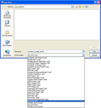
Figure 31: Saving ArchiCAD file in IFC2x3
Default ArchiCAD settings, apart from the exceptions noted below, have been applied in saving the native file to IFC, as shown in the screenshots below. To examine interoperability of 2D information contained in the 3D model, 2D Elements option was selected, as shown in Figure 33.
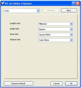
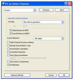
|
Figure 32: ArchiCAD IFC2x Units settings |
|
Figure 33: ArchiCAD IFC2x 'Export' settings with '2D Elements' option selected
|
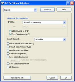
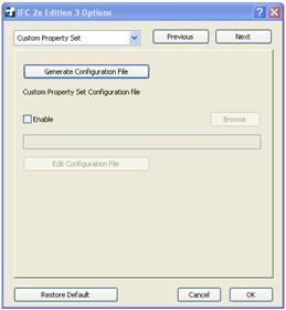
|
Figure 34: ArchCAD IFC2x 'Export' settings with '2D Elements' option unselected |
|
Figure 35: ArchiCAD IFC2x Custom Pset settings |
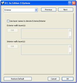
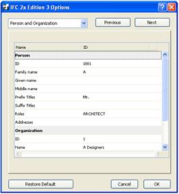
|
Figure 36: ArchiCAD IFC2x Exterior settings |
|
Figure 37: ArchiCAD IFC2x Person and Organization settings |
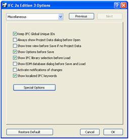
Figure 38: ArchiCAD IFC2x Miscellaneous settings
The remaining settings utilised in saving the authoring application file to IFC are illustrated above in Figure 35 through Figure 38.
2.2 2D Information within 3D Model
The examples below illustrate interoperability issues with 2D information included within 3D parametric model file. The benchmark has been the native ArchiCAD model as illustrated in Figure 39.

Figure 39: Native ArchiCAD model, 2D view opened in ArchiCAD
The intention of this exercise was to examine the model in conjunction with each of the software listed in Table 2. Each software application was used to open two types of the IFC file saved from the native Start-Up Model: (1) with '2D Elements' option selected, and (2) 2D Elements option unselected, as shown in Figure 33 and Figure 34 respectively.
Example 1
The process of evaluation started with Solibri Model Viewer. It has not been possible however, to view the 2D information using this application; hence the related 2D interoperability issues were not examined.
While opening IFC model in DDS-CAD Viewer, saved from ArchiCAD to IFC with 2D Elements selected from Options, a number of error messages has appeared as illustrated in Figure 40, which prevented the file from opening.
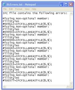
Figure 40: IFC file errors (with '2D Elements' option selected) in DDS-CAD Viewer
The 2D IFC model opened in DDS-CAD Viewer, saved from ArchiCAD to IFC with 2D Elements unselected from Options, as shown in Figure 41 has exhibited the following problems when visually compared with the native 2D model:
- missing dimensions
- missing window and door markers
- missing elevation marker
- missing content of architects_2d_backgrounds layer with the original 2D CAD floor plan drawing
- up-side-down and miss-aligned numbering of the grid lines (from 10 to 13)
- changed graphics of bathroom plumbing fixtures
- changed graphics of doors with no door swings shown
- line thicknesses not maintained
- line colours changed
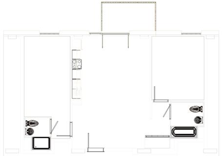
Figure 41: Start-Up Model - IFC file (with 2D Elements option unselected) 2D view opened in DDS-CAD Viewer
Example 3
The 2D IFC model opened in Nemetschek IFC Viewer as shown in Figure 42 and Figure 43 has shown a number of interoperability inconsistencies during visual comparison with the native 2D model:
- portions of the 2D overlay corrupted (visible diagonal lines)
- text generally miss-aligned /corrupted
- missing dimensions and elevation marker
- missing window and door markers
- changed graphics of bathroom plumbing fixtures
- changed graphics of doors with no door swings shown
- line thicknesses not maintained and line colours changed
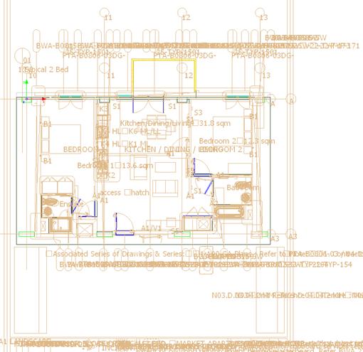
Figure 42: Start-Up Model - IFC file (with 2D Elements option selected) 2D view opened in Nemetschek IFC Viewer
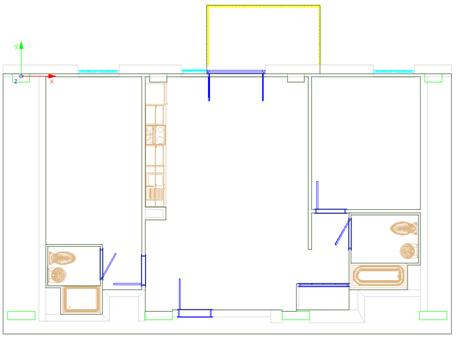
Figure 43: Start-Up Model - IFC file (with 2D Elements option unselected) 2D view opened in Nemetschek IFC Viewer
It was not possible to view the 2D information in IFC Engine Viewer; therefore, 2D potential interoperability has not been examined using this application.
The examination continued with viewing the IFC 2D files using proprietary software applications utilised by Architects-Concept Design, Civil & Structural Engineers, Building Services Engineers, Envelope Designers, and Contractors.
The 2D IFC model opened in ArchiCAD has shown the following interoperability inconsistencies as a result of visual comparison of the 2D model against the native one:
- portions of the 2D overlay corrupted (visible diagonal lines)
- missing text
- missing dimensions
- missing window and door markers
- missing elevation marker
- changed graphics of bathroom plumbing fixtures and balcony flooring
- 3Dmodel door swings missing
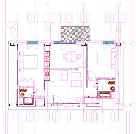
Figure 44: Start-Up Model - IFC file (with 2D Elements option unselected) 2D view opened in ArchiCAD
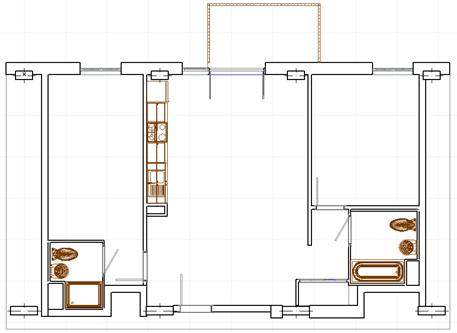
Figure 45: Start-Up Model - IFC file (with 2D Elements option selected) 2D view opened in ArchiCAD
The 2D IFC model opened in Bentley Structural Modeler as shown in Figure 47 and Figure 48 has exhibited a number of interoperability inconsistencies during visual comparison with the native 2D model:
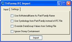
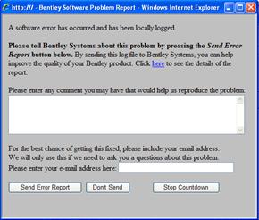
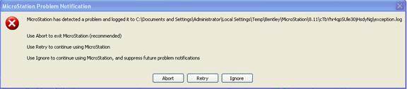
Figure 46: Error messages while retrieving Start-Up Model IFC file (with 2D Elements option selected) 2D view opened in Bentley Microstation Structural Modeler
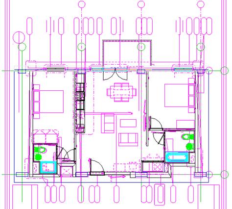
Figure 47: Start-Up Model - IFC file (with 2D Elements option selected) 2D view opened in Bentley Microstation Structural Modeler
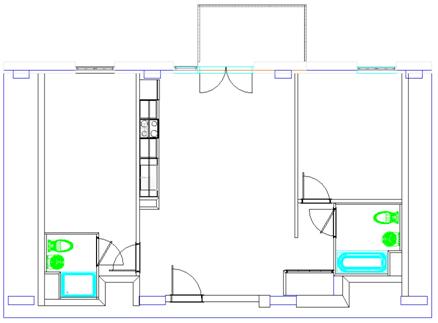
Figure 48: Start-Up Model - IFC file (with 2D Elements option unselected) 2D view opened in Bentley Microstation Structural Modeler
Example 7
It was not possible to open the IFC file in Autodesk Revit MEP when saved from ArchiCAD to IFC with 2D Elements selected from Options, and 77 errors and 933 warnings has appeared during the attempts of opening this fairly simple model.
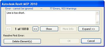
Figure 49: Autodesk Revit MEP error and warnings message
The model with 2D Elements unselected in ArchiCAD IFC model options was opened in Autodesk Revit MEP using Open>IFC opens and IFC file command. Warnings had been posted by the systems as show in Figure 50. These were ignored, as per recommendations in the automated message.
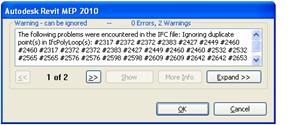
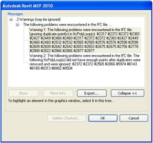
Figure 50: Warnings posted prior to opening the model in Autodesk Revit MEP
The 2D IFC model with 2D Elements option selected opened with difficulties in Autodesk Revit MEP has shown the following interoperability inconsistencies resulting from visual comparison of the 2D model against the native one:
- missing dimensions
- missing window and door markers
- missing elevation marker
- missing original 2D CAD floor plan drawing placed on architects_2d_backgrounds layer
- missing grid lines; the only information retained are the grid lines numbers/letters
- columns not separated from walls
- changed graphics of bathroom plumbing fixtures
- line thicknesses not maintained
- No line colours
- bathroom doors fully open, not 30º
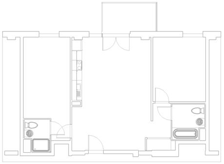
Figure 51: Start-Up Model - IFC file (with 2D Elements option unselected) 2D view opened in Autodesk Revit MEP
The successful import of the IFC file into Vectorworks was only possible after upgrading the software with Service Pack 4. It has generated identical 2D view for 2D Elements selected or unselected while saving to IFC from ArchiCAD. The following differences from the native file have been recorded:
- missing dimensions
- missing grid lines
- missing window and door markers
- missing elevation marker
- missing original 2D CAD floor plan drawing placed on architects_2d_backgrounds layer
- changed graphics of bathroom plumbing fixtures
- door swings missing
- line thicknesses not maintained
- line colours changed

Figure 52: Start-Up Model - IFC file (identical with 2D Elements option selected and unselected) 2D view opened in Vectorworks with Service Pack 4
The 2D IFC model opened in Constructor, as shown in Figure 53 and Figure 54, has shown a number of interoperability inconsistencies during visual comparison with the native 2D model:
- some door frames projected from the wall
- line representations, i.e. dashed line for balcony balustrade
- range of other issues similar to experienced in ArchiCADs Example 5.
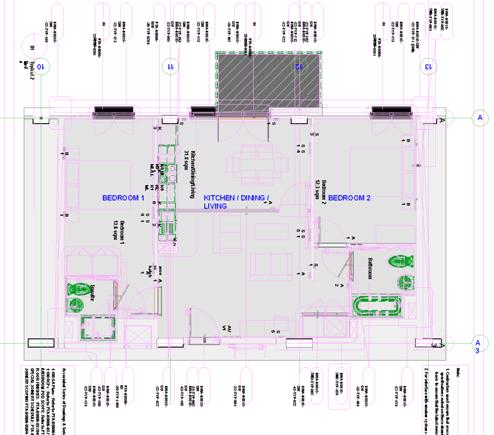
Figure 53: Start-Up Model - IFC file (with 2D Elements option selected) 2D view opened in Constructor
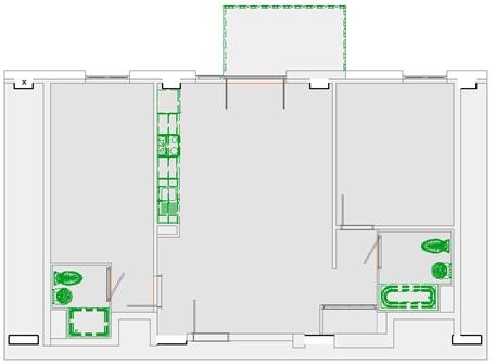
Figure 54: Start-Up Model - IFC file (with 2D Elements option unselected) 2D view opened in Constructor
Example 10
The 2D IFC model opened in Google SketchUp with IFC2SKP plug-in (Secom Co. Ltd., 2010), as shown in Figure 55, has shown a number of interoperability inconsistencies during visual comparison with the native 2D model:
- missing dimensions
- missing grid lines
- missing window and door markers
- missing elevation marker
- missing original 2D CAD floor plan drawing placed on architects_2d_backgrounds layer
- missing bathroom plumbing fixtures
- missing kitchen sink with the cabinet
- door swings missing
- line thicknesses not maintained and line colours changed
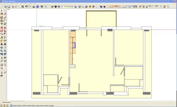
Figure 55: Start-Up Model: IFC file (with 2D Elements option selected or unselected) 2D view opened in SketchUp
2.3 IFC File Analyzer: Spreadsheet of Start-Up Model IFC File
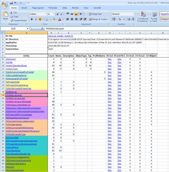
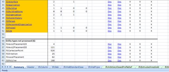
Figure 56: IFC File Analyzer, Start-Up Model - Summary sheet
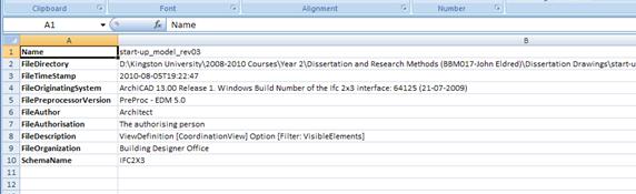
Figure 57: IFC File Analyzer, Start-Up Model - Header sheet
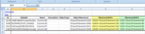
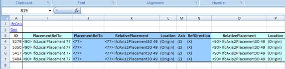
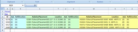
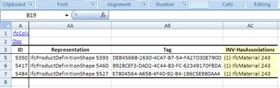
Figure 58: IFC File Analyzer, Start-Up Model - IfcColumn sheet
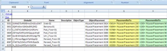
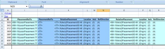
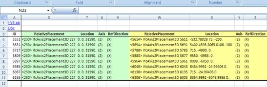
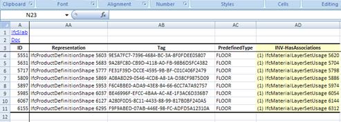
Figure 59: IFC File Analyzer, Start-Up Model - IfcSlab sheet
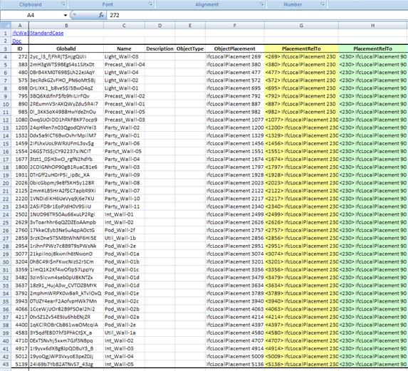
Figure 60: File Analyzer, Start-Up Model - IfcWall sheet (part 1 of 4)
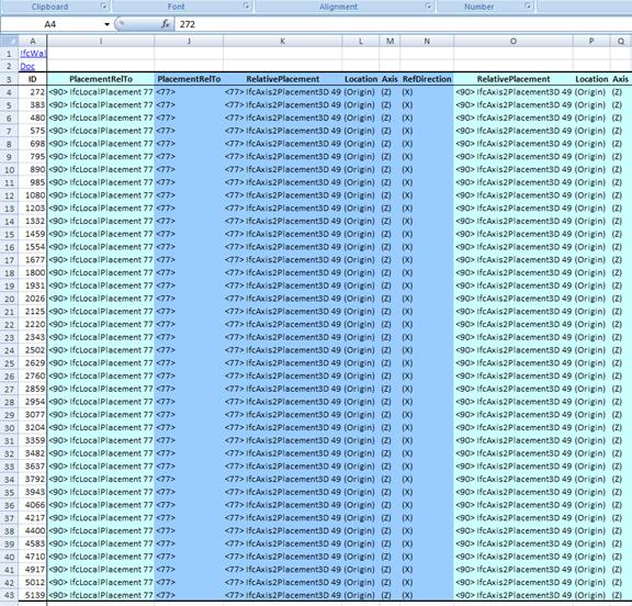
Figure 61: File Analyzer, Start-Up Model - IfcWall sheet (part 2 of 4)
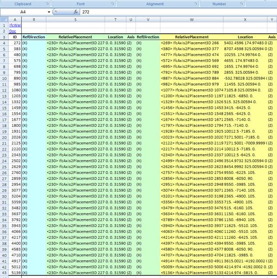
Figure 62: File Analyzer, Start-Up Model - IfcWall sheet (part 3 of 4)
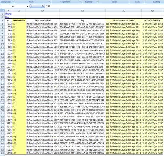
Figure 63: File Analyzer, Start-Up Model - IfcWall sheet (part 4 of 4)
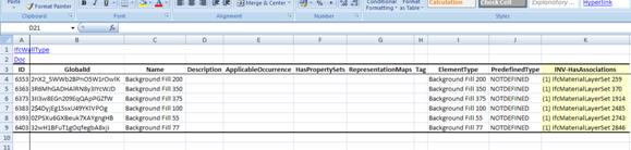
Figure 64: File Analyzer, Start-Up Model - IfcWallType sheet
2.4 Proprietary Software Settings vs. Accurate IFC Model
In attempt of preserve the models integrity while importing, exporting or otherwise exchanging files utilising ArchiCAD, Extended Properties feature was selected, as shown in Figure 65. This was done specifically in attempt to preserve integrity of the model. According to Graphisoft US Inc. (2009) it is advantageous to use this setting when expecting that IFC project would be doing a round trip, meaning exporting the IFC model and merging it back into ArchiCAD.
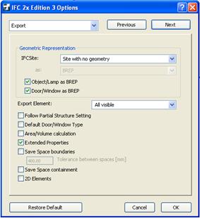
Figure 65: ArchiCAD IFC2x Export settings with Extended Properties selected
The results returned mayor inconsistencies or corrupted portions of the model, as shown in Figure 66 and Figure 67 and described below. This was unexpected, particularly in light of Extended Properties feature which was expected to enhance the model rather than diminishing it.
- a number of object attributes names are missing or changed
- sink with the cabinet, cabinets and wall cabinets considerably shifted along the wall out of its original position, or missing
- refrigerator and stove are missing
- tub and shower re-positioned of its original location partially to the adjacent housing unit
- toilets have been shifted. The one in Bathroom 1 clashes with the sing, the Bathroom 2 toilet clashes with the wall
- doors in Bathrooms and Bedrooms have hinges in opposite side of door frame and open in opposite directions
- balcony balustrades missing
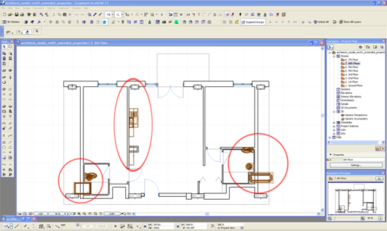
Figure 66: Architects start-up IFC model plan opened in ArchiCAD with Extended Properties option selected

Figure 67: Architects start-up IFC model opened in ArchiCAD with Extended Properties option selected
Apart from the comments noted earlier in the text, an additional issue has emerged, being the altered internal door swings. This issue has not been only about missing design information, but about communicating incorrect information. If the errors like this are not mitigated they could lead to substantial cost and programme/schedule implications. The subject project involves over 10,000 doors, and the impact of incorrectly ordered joinery based on corrupted construction drawings could be significant. It is therefore prudent that interoperability issues are thoroughly monitored by checking, in the first instance, software settings while managing a file exchange.
2.5 Separating Elements or Objects
The initial evaluation of Constructor has shown close resemblance of the IFC file opened in ArchiCAD to the original model. This was expected, as Constructor is based on technologies developed by Graphisoft. There has been only a slight deviation in colour representation of the building materials, and all initially indicated that there are no 3D geometry issues.
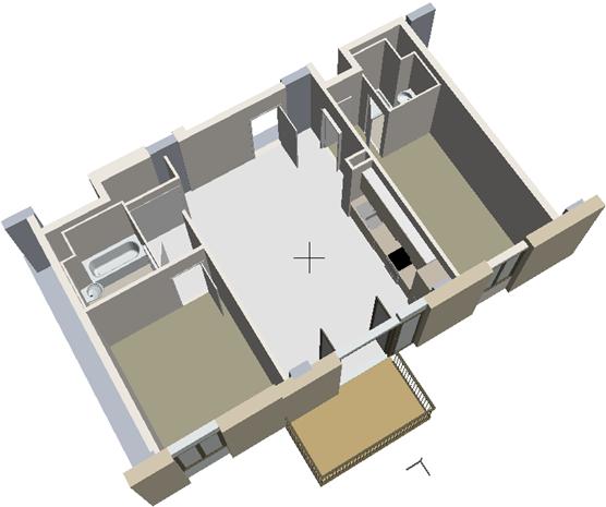
Figure 68: Start-Up IFC model opened in Constructor
This however, has not been a case, as various doors with the frames were found out of position, as illustrated in Figures XX, YY and ZZ.
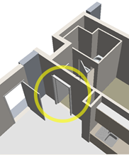
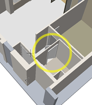
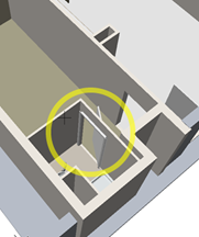
Figure 69: Start-Up IFC model opened in Constructor - details
Summarising the investigative approach above, it is clear that IFC is not sufficiently mature to relay on when it comes to exchanging 2D information. In contrast, IFC 3D model has been accurate when utilising the applications above, with an exemption of issues experienced in Constructor. To address the Constructor issue, the subject model was simplified by stripping the adjacent content and leaving only the parts of the model in question. In the end, the issue has been resolved by separating the problem elements from the rest of the model content.
|
|
|

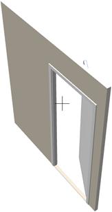

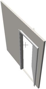
(1) (2)
Figure 70: Start-Up IFC model opened in (1) ArchiCAD and (2) Constructor and as extract from the complete model
|
|
|

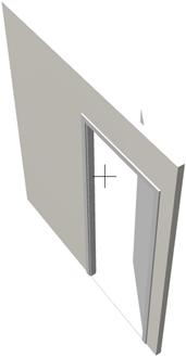

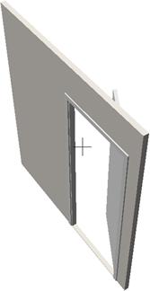
(1) (2)
Figure 71: Start-up IFC model opened in (1) ArchiCAD and (2) Constructor and as a single-door-in-the-wall model
2.6 Non_Standard Psets
As identified in 2D model analysis for SketchUp with IFC2SKP plug-in (Secom Co. Ltd., 2010), Figure 72, the IFC model has been lacking bathroom plumbing fixtures, kitchen sink and the kitchen sink cabinet. There have been also other deviations in appearance, and these are listed below:
- instances of materials being represented in different colours/shades, as these should be identical because they carry the same specification
- no differentiation in colour in floor materials in the rooms and the balcony, as these should be contrasting due to different specifications
- no differentiation in colour of wall materials, with only structural elements (rectangular columns) being differentiated.
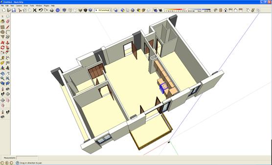
Figure 72: Start-up IFC model opened in SketchUp with IFC2SKP plug-in
IFC File Analyzer was utilised to read the IFC file in question and generate Excel spreadsheets for analysis.
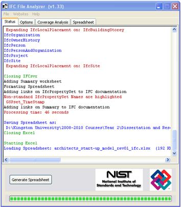
Figure 73: IFC File Analyzer: Generating spreadsheet from Start-Up Model IFC file
The spreadsheet generation was accompanied by IFC File Analyzer (Lipman, 2009) report containing details of the conversion process, as shown in Figure 73. The report disclosed that Non-standard IfcPropertySet Names are highlighted in the spreadsheet. The Excel spreadsheet has listed standard IfcPropertySet Names, highlighted non-standard IfcPropertySet Names, Entity types not processed, and provided the associated detail like Entity Count and Entity Name of processed and un-processed Entity types, all shown in Figure 74.
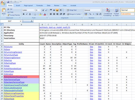
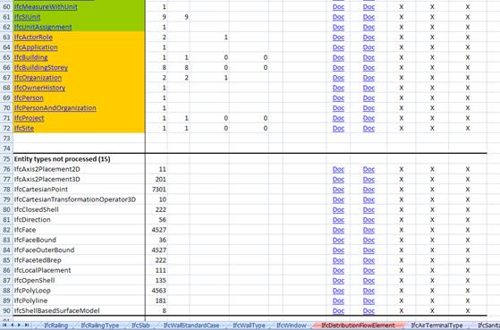
Figure 74: IFC File Analyzer: Excel spreadsheet generated from Start-Up Model IFC file
The analysis have revealed that Start-Up Model included eighty Entity Types, but only eleven of these were classified as Standard.
Further tests involved replacing selected non-standard Entity Types with standard ones in IFC code. In this process of selecting the Entity Types, the particular attention was drawn to Architects (AR_CD) model objects which, based on visual examination, did not translate well into IFC when viewed in ArchiCAD and SketchUp as shown in Figure 66/Figure 67 and Figure 72 respectively. These objects were found in the Excel spreadsheet under the non-standard IfcPropertySet named IfcDistributionFlowElement. The objects were: Toilet-01, Toilet-02, Wash_Basin-01, Wash-Basin-02, Shower-01, Tub-01, and Sink-01, as shown in Figure 75.
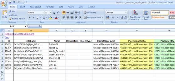
Figure 75: File Analyzer: Excel spreadsheet listing objects with a non-standard IfcPropertySet
In order to address interoperability issues found in SketchUp, the listing of standard IfcPropertySet names found in IFC File Analyzer (Lipman, 2009) spreadsheet was first compared with the listing of standard IfcPropertySet names in SketchUp.
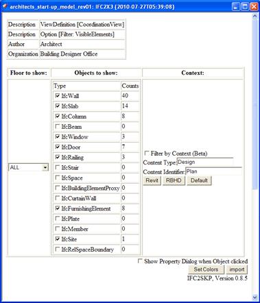
Figure 76: SketchUp IFC Psets of Start-Up Model
The non-standard IfcPropertySet named IfcDistributionFlowElement, as seen in ArchiCAD, was not found on the list initiated by SketchUp and consequently renamed to the standard Pset IfcFurnishingElement. In the end, all of the eight instances of IfcDistributionFlowElement Pset have been replaced with IfcFurnishingElement.
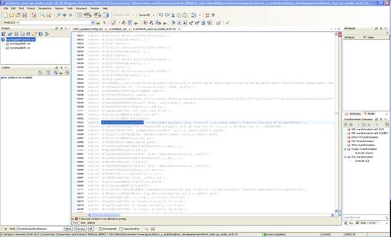
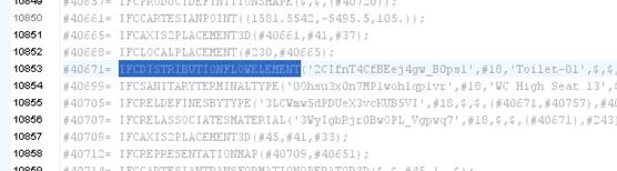
Figure 77: Start-Up Model IFC file open in Oxygen XML - one of eight instances of non-standard IfcDistributionFlowElement Pset
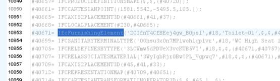
Figure 78: Start-Up Model IFC file open in Oxygen XML - one of eight instances of non-standard IfcDistributionFlowElement Pset replaced with standard IfcFurnishingElement
The revised IFC file was opened in SketchUp with the results shown in Figure 79 and Figure 80.
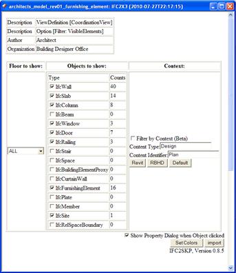
Figure 79: SketchUp IFC Pset of Start-Up Model revised
Additional eight IfcFurnishingElement Psets appeared in SketchUp IFC import window giving the total of sixteen Psets of that element.
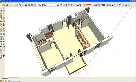
Figure 80: Start-up IFC model opened in SketchUp with IfcDistributionFlowElement replaced with IfcFurnishingElement
The model has been generated utilising the revised IFC file, and based on its visual examination, the model geometry has no longer shown irregularities. The previously omitted bathroom plumbing fixtures, kitchen sink and the kitchen sink cabinet are now clearly in place, along with the remaining improvements to the issues listed in the beginning of this sub-section.
Appendix 2 - Bibliography
Adachi, Y. (2010) Research on Building Information Model and IFC. Available at:http://www.secom.co.jp/isl/e2/research/cs/report02/index.html#Overview (Accessed: 29 June 2010).
Autodesk Inc. (2010a) AutoCAD. Coming Soon to Your Mac. Available at:http://usa.autodesk.com/adsk/servlet/pc/index?id=15421056&siteID=123112 (Accessed: 10 September 2010).
Autodesk Inc. (2010b) Autodesk Navisworks Products. Available at:http://usa.autodesk.com/adsk/servlet/pc/index?siteID=123112&id=10571060 (Accessed: 18 June 2010).
Bentley Systems Incorporated. (2008) 'IFC Position Paper', Bentley Systems Incorporated, [Online]. Available at:http://ftp2.bentley.com/dist/collateral/whitepaper/Building_IFC_Position_Paper_whitepaper_eng.pdf (Accessed: 3 December 2009).
buildingSMART (2009a) IFC2x Edition 3. Available at:http://www.iai-tech.org/downloads/ifc/ifc2x3/IFC2x3_Final_HTML_distribution.zip/view (Accessed: 28 May 2010).
buildingSMART. (2009b) 'IFC 2x Edition 3 Model Implementation Guide', [Online]. Available at:http://www.iai-tech.org/downloads/accompanying-documents/guidelines/IFC2x%20Model%20Implementation%20Guide%20V2-0b.pdf/view?searchterm=model%20implementation%20guide (Accessed: 11 November 2009).
buildingSMART (2009c) IFC Overview Summary Available at:http://www.iai-tech.org/products/ifc-overview (Accessed: 22 June 2010).
buildingSMART (2009d) Information Delivery Manual. Available at:http://www.iai.no/idm/ (Accessed: 12 May 2010).
buildingSMART (2010a) buildingSMART. Available at:http://www.buildingsmart.org.uk/buildingSMART/what-is-the-iai/ (Accessed: 29 June 2010).
buildingSMART (2010b) IFC Certified Software. Available at:http://www.ifcwiki.org/index.php/IFC_Certified_Software (Accessed: 28 February 2010).
buildingSMART (2010c) IIfcWall. Available at:http://www.iai-tech.org/ifc/IFC2x4/alpha/html/ifcsharedbldgelements/lexical/ifcwall.htm (Accessed: 28 June 2010).
buildingSMART (2010d) Information Delivery Manual (IDM) Available at:http://www.buildingsmart.com/content/process (Accessed: 11 February 2010).
buildingSMART (2010e) International Framework for Dictionaries (IFD). Available at:http://www.buildingsmart.com/content/ifd (Accessed: 11 February 2010).
buildingSMART (2010f) Model - Industry Foundation Classes (IFC). Available at:http://www.buildingsmart.com/bim (Accessed: 16 September 2009).
buildingSMART Alliance (2010) Frequently Asked Questions About the National BIM Standard. Available at:http://www.buildingsmartalliance.org/index.php/nbims/faq/#faq1 (Accessed: 09 February 2010).
Burns, R. B. (2000) Introduction to Research Methods. London: Sage Publications Ltd.
Cheng, J., Kumar, B. and Law, K. H. (2003) 'A Question Answering System for Project Management Applications', ScienceDirect, 277-289, [Online]. Available at:http://www.sciencedirect.com/science?_ob=ArticleURL&_udi=B6X1X-497WRKV-4&_user=10&_coverDate=10%2F31%2F2002&_rdoc=1&_fmt=high&_orig=search&_sort=d&_docanchor=&view=c&_searchStrId=1379088822&_rerunOrigin=google&_acct=C000050221&_version=1&_urlVersion=0&_userid=10&md5=1f5eb584c99ccbd7301d193a365ee069 (Accessed: 17 June 2010).
Douglas, A. (2010) 'Collaboration in the New AEC World', AECbytes, [Online]. Available at:http://www.aecbytes.com/viewpoint/2010/issue_52_pr.html (Accessed: 5 May 2010).
Eastman, C. (2009) Building Information Modeling. What is BIM? Available at:http://bim.arch.gatech.edu/?id=402 (Accessed: 14 May 2010).
Eastman, C., Sacks, R., Jeong, Y.-S. and Kaner, I. (2008) 'Building Information Modeling (BIM) for Architectural Precast Concrete', [Online]. Available at:http://www.spur.org/files/pankow/08-06NIBSCPFFinalReport3-08.pdf (Accessed: 30 August 2010).
Encyclopaedia Britannica eb.com (2010) History & Society: Tower of Babel. Available at:http://www.britannica.com/EBchecked/topic/47421/Tower-of-Babel (Accessed: 23 May 2010).
Gallaher, M. P., OConnor, A. C., Jr., J. L. D. and Gilday, L. T. (2004) 'Cost Analysis of Inadequate Interoperability in the U.S. Capital Facilities Industry', NIST - U.S. Department of Commerce Technology Administration National Institute of Standards and Technology, [Online]. Available at:http://www.bfrl.nist.gov/oae/publications/gcrs/04867.pdf (Accessed: 18 June 2010).
Gökce, K. U., Scherer, R. J. and Dikbaş, H. A. (2007) 'IFC Based Computer-Integrated Construction Management Model', IFIP International Federation for Information Processing: A springer Series in Computer Science, 119-124, [Online]. Available at:http://itc.scix.net/data/works/att/w78-2007-018-187-Gkce.pdf (Accessed: 24 June 2010).
Graphisoft US Inc. (2009) 'IFC 2x3 Reference Guide for ArchiCAD 13', ArchicadWiki, [Online]. Available at:http://www.archicadwiki.com/IFCForAC13OrOlder?action=AttachFile&do=view&target=IFC2x3Guide13.pdf (Accessed: 21 June 2010).
Hudak, P. and Jones, M. P. (1994) 'Haskell vs. Ada vs. C++ vs. Awk vs. ... An Experiment in Software Prototyping Productivity', [Online]. Available at:http://docs.google.com/viewer?a=v&q=cache:PZ7XZKaViQwJ:citeseerx.ist.psu.edu/viewdoc/download%3Fdoi%3D10.1.1.117.1208%26rep%3Drep1%26type%3Dpdf+%22an+experiment+in+software+prototyping+productivity%22+pdf&hl=en&pid=bl&srcid=ADGEESjMDc3UQqunAbgwH9LjzGpvuGNj8u13SrMPQ6HGx4YON0SEcj_49T_Mw3f7Vgw1xQ1jVvz4ENsUHIe0YyfYI9KkumOAY5h7QTH1VbX6NXgHlBLsSqDhkQzmAPoisDkFn_hJu0UE&sig=AHIEtbQa1KJ765HLG-C-X0RUOSSy9VljEA (Accessed: 28 July 2010).
IFDWeb (2010) Home Page. Available at:http://www.ifd-library.org/index.php?title=Home_Page (Accessed: 2 May 2010).
International Alliance for Interoperability. (1999) 'IFC Object Model Guide', [Online], 2. Available at:http://www.bbs-slama.com/Projets/CLAIRE/Rapport/Documentation/IFC_R2_V2_ObjectModelGuide_A4.pdf (Accessed: 11 December 2009).
International Alliance for Interoperability. (2007) 'ifcXML Implementation Guide', [Online]. Available at:http://www.iai-tech.org/downloads/accompanying-documents/guidelines/ifcXML%20Implementation%20Guide%20v2-0.pdf/index_html (Accessed: 11 November 2009).
International Organization for Standardization (2010a) About ISO. Available at:http://www.iso.org/iso/about.htm (Accessed: 10 February 2010).
International Organization for Standardization (2010b) Discover ISO. Available at:http://www.iso.org/iso/about/discover-iso_why-standards-matter.htm (Accessed: 12 March 2010).
International Organization for Standardization (2010c) STEP. Available at:http://www.iso.org/iso/iso_cafe_step.htm (Accessed: 22 May 2010).
Jadid, M. N. and Idrees, M. M. (2007) 'Cost estimation of structural skeleton using an interactive automation algorithm: A conceptual approach', Automation in Construction, 797-805, [Online]. Available at:http://www.sciencedirect.com/science?_ob=MImg&_imagekey=B6V20-4NC5V3J-2-N&_cdi=5688&_user=6733290&_pii=S0926580507000192&_orig=search&_coverDate=09%2F30%2F2007&_sk=999839993&view=c&wchp=dGLzVzz-zSkzV&md5=c71f60fe4fbdf4385b8f07a7a4d41a35&ie=/sdarticle.pdf (Accessed: 11 December 2009).
Khemlani, L. (2004) 'The IFC Building Model: A Look Under the Hood', AECbytes, [Online]. Available at:http://www.aecbytes.com/feature/2004/IFCmodel_pr.html (Accessed: 12 November 2009).
Khemlani, L. (2007) 'AIA TAP 2007 Conference', AECbytes, [Online]. Available at:http://www.aecbytes.com/newsletter/2007/issue_31_pr.html (Accessed: 11 December 2009).
Khemlani, L. (2010) 'AutoCAD Comes to the Mac and the iPad!', AECbytes, [Online]. Available at:http://www.aecbytes.com/newsletter/2010/issue_46.html (Accessed: 10 September 2010).
Kulusjärvi, H., Widney, K. and Jauhiainen, J. (2010) 'Solibri Model Checker: Introduction to Information Takeoff', [Online]. Available at:http://www.google.com/url?sa=t&source=web&cd=1&ved=0CBUQFjAA&url=http%3A%2F%2Fsolibri.fi%2Fdocuments%2Fenglish-material%2Fintroduction-to-information-takeoff-with-solibri-model-checker-v6-pdf%2Fdownload.html&rct=j&q=solibri%20model%20checker%20introduction%20to%20information%20takeoff&ei=36tWTLCaLY-i0gTmtND3Ag&usg=AFQjCNFnmOTBaZzrcGKu7syzzr5rffprmg (Accessed: 30 June April 2010).
Lipman, R. (2009) IFC File Analyzer. (Version 1.33) [Computer program]. Available at:http://ciks.cbt.nist.gov/cgi-bin/ctv/ifa_request.cgi (Accessed: 06 July 2010).
National Institute of Building Sciences (2010) About the National BIM Standard®. Available at:http://www.buildingsmartalliance.org/index.php/nbims/about/ (Accessed: 18 June 2010).
Pollalis, S. N. (2005) '10 Exchange Square, London: Information Technology for Collaboration', [Online]. Available at:http://www.gsd.harvard.edu/people/faculty/pollalis/cases/BL-CaseStudy-mar-2005.pdf (Accessed: 15 April 2009).
Qizhen, Y., Song, J., Sitoh, P., Babu, R. and Jian, X. X. (2001) 'Capability Development on IFC and ifcXML Technologies', SIMTach Technical Report (MIT/01/033/ITAC), [Online]. Available at:http://www.simtech.a-star.edu.sg/Research/TechnicalReports/TR0100.pdf (Accessed: 12 May 2010).
Sabol, L. (2008) 'Challenges in Cost Estimating with Building Information Modeling', Design + Construction Strategies: The Power of Process in the Build Environment, [Online]. Available at:http://www.dcstrategies.net/pdf/2_sabol_cost_estimating.pdf (Accessed: 15 February 2010).
Secom Co. Ltd. (2010) IFC2SKP Plug-in. (Version 0.85 Beta) [Computer program]. Available at:http://www.ohyeahcad.com/ifc2skp/index.php (Accessed: 23 May 2010).
Serror, M. H. (2006) 'Building on IT/IFC: Shared Computer-Aided Structural Design Model for Construction Industry', ARPU: Association of Pacific Rom Universities, [Online]. Available at:http://dir.u-tokyo.ac.jp/kokusai/reports/Fullpaper.pdf (Accessed: 13 May 2010).
Solibri, I. (2010) BIM is Here: Are You Ready? Available at:http://www.solibri.com/documents/1-2010/solibri-magazine-1-2010-page-4/download.html (Accessed: 29 July 2010).
Solibri Inc. (2010) Solibri IFC Optimizer. (Version Version No. not available) [Computer program]. Available at:http://www.solibri.com/solibri-ifc-optimizer.html (Accessed: 06 Jannuary 2010).
Sperberg-McQueen, C. M. and Thompson, H. (2000) XML Schema. Available at:http://www.w3.org/XML/Schema#dev (Accessed: 11 February 2010).
Staub-French, S., Fisher, M., Kunz, J., Ishii, K. and Paulson, B. (2003) 'A feature ontology to support construction cost estimating', Artificial Intelligence for Engineering Design, Analysis and Manufacturing, [Online]. Available at:http://www.civil.ubc.ca/people/faculty/ssf/AIEDAM_17%282%29.pdf (Accessed: 16 January 2010).
Summers, M. (2008) CAD Drafting Software Available at:http://www.ebusiness-articles.com/articledetail.php?artid=18183&catid=37&title=CAD+Drafting+Software (Accessed: 28 June 2010).
The American Institute of Architects. (2007a) 'Integrated Project Delivery: A Guide', [Online]. Available at:http://www.msa-ipd.com/IPD_Guide_2007.pdf (Accessed: 26 May 2010).
The American Institute of Architects. (2007b) 'Integrated Project Delivery: A Working Definition', [Online]. Available at:http://www.ipd-ca.net/images/Integrated%20Project%20Delivery%20Definition.pdf (Accessed: 21 February 2010).
The National Institute of Building Sciences. (2005) 'Charter for the National Building Information Model (BIM) Standard, December 15, 2005', NIST - Building and Fire Research Laboratory, [Online]. Available at:http://www.buildingsmartalliance.org/client/assets/files/bsa/NBIMS_Charter.pdf (Accessed: 23 May 2010).
The National Institute of Standards and Technology. (2010a) 'BFRL Project: Methods and Metrics for Conformance Testing for Construction Project Data Standards', NIST - Building and Fire Research Laboratory, [Online]. Available at:http://www.nist.gov/bfrl/construction_productivity/conformance-testing-project.cfm (Accessed: 12 May 2010).
The National Institute of Standards and Technology (2010b) CIS/2 and IFC - Product Data Standards for Structural Steel. Available at:http://cic.nist.gov/vrml/cis2.html (Accessed: 15 May 2010).
The National Institute of Standards and Technology (2010c) NIST General Information. Available at:http://www.nist.gov/public_affairs/general_information.cfm (Accessed: 09 June 2010).
Thomson Reuters Corporation (2010) EndNote (Version X4.0) [Computer program]. Available at:http://www.endnote.com/ (Accessed: 06 June 2010).
Tiwari, S., Odelson, J., Watt, A. and Khanzode, A. (2009) 'Model Based Estimating to Inform Target Value Design', AECbytes, [Online]. Available at:http://www.aecbytes.com/buildingthefuture/2009/ModelBasedEstimating_pr.html (Accessed: 16 September 2009).
W3C (2009a) About W3C. Available at:http://www.w3.org/Consortium/ (Accessed: 21 May 2010).
W3C (2009b) W3C Mission. Available at:http://www.w3.org/Consortium/mission (Accessed: 21 May 2010).
Weise, M., Liebich, T. and Wix, J. (no year) 'Integrating Use Case Definitions for IFC Developments', [Online]. Available at:http://www.inpro-project.eu/media/Integrating_UseCase_def.pdf (Accessed: 18 July 2010).
Wikipedia Foundation Inc. (2010) 'Kernel (computing)', [Online]. Available at:http://en.wikipedia.org/wiki/Kernel_%28computing%29 (Accessed: 11 February 2010).
Yang, Q. (2003) 'IFC-Compliant Design Information Modeling and Sharing', [Online], 8. Available at:http://www.google.com/#hl=en&q=standard+and+non-standard+IFC+property+set+name&aq=f&aqi=m1&aql=&oq=&gs_rfai=&pbx=1&fp=8631cdd35a4d476d (Accessed: 17 July 2010).
Yang, Q. Z. and Zhang, Y. (2006) 'Semantic Interoperability in Building Design: Methods and Tools', ScienceDirect, 1099-1112, [Online]. Available at:http://www.sciencedirect.com/science?_ob=ArticleURL&_udi=B6TYR-4KJ0SV8-1&_user=10&_coverDate=10%2F31%2F2006&_rdoc=1&_fmt=full&_orig=search&_cdi=5625&_sort=d&_docanchor=&view=c&_searchStrId=1367577742&_rerunOrigin=scholar.google&_acct=C000050221&_version=1&_urlVersion=0&_userid=10&md5=664945e1420485ecc4a0f133be405cee (Accessed: 19 November 2009).
Young, N. W. J., Jones, S. A. and Bernstein, H. M. (2007) 'Interoperability in the Construction Industry', SmartMarket Report, [Online]. Available at:http://construction.ecnext.com/mcgraw_hill/includes/SMRI.pdf (Accessed: 11 May 2010).